Soft-top convertible roof

a convertible roof and soft-top technology, applied in the field of convertible roofs, can solve the problems of presenting a packaging (stowing) difficulty, affecting the appearance of the vehicle, and affecting the appearance of the vehicle, and achieve the effect of shortening the length

Inactive Publication Date: 2009-07-14
SPECIALTY VEHICLE ACQUISITION
View PDF21 Cites 19 Cited by
  • Summary
  • Abstract
  • Description
  • Claims
  • Application Information

AI Technical Summary

Benefits of technology

[0004]Most traditional convertible roofs are stowed in a bootwell or stowage compartment that is located aft of a passenger compartment in the vehicle. A boot or tonneau cover is then used to cover the bootwell and conceal the convertible roof from view and / or protect the stowed roof from the environment. Optionally, a portion of the convertible roof can be visible when in the stowed position and provide a desired appearance for the vehicle.
[0006]The available space for the stowage compartment in a vehicle, however, may be at a premium. That is, while it is desirable to provide a vehicle with a convertible roof, it is also desirable to provide sufficient storage space in the vehicle for use in storing objects other than the convertible roof. Thus, it would be advantageous to reduce the packaging space required to stow the convertible roof while increasing the available space for other purposes, such as maintaining or increasing the size of the passenger compartment and / or the size of the general storage area or trunk of the vehicle when produced with a convertible roof.
[0008]In one aspect of the present teachings, the retraction of the convertible roof is a two-step process. In the first step, the sections of the segmented rearmost roof bow are moved relative to one another to take an adjacent position and shorten the length. This motion can be accomplished while the rest of the top stack mechanism remains stationary. In the second step of the retraction process, the sections of the segmented roof bow can be held in the adjacent position while the rest of the top stack mechanism and the segmented roof bow retracts into the stowage well. In another aspect of the present teachings, the segmented sections of the rearmost roof bow move from an aligned position to a shortened, adjacent position as the top stack mechanism retracts into the stowage well. In this teaching, the segmented sections move relative to one another as the rear roof rail moves. Thus, in this aspect, the shortening of the rearmost roof bow can be accomplished in conjunction with the rotation of the rearmost roof rail between the raised and stowed positions.
[0009]This shortening of the rearmost roof bow advantageously reduces the packaging space required for a convertible roof employing such a segmented rearmost roof bow. Thus, in a convertible roof according to the present teachings, the length of the rearmost roof bow is shortened during the retraction process to allow the convertible roof to stow more compactly. The ability to shorten the length of the rearmost roof bow during the retraction process enables a longer rearmost roof bow to be implemented when the convertible roof is in the raised operative position to provide an aesthetically desirable appearance. For example, the use of an extended length rearmost roof bow can facilitate the appearance of a fastback vehicle wherein the roof line extends rearwardly a significant distance toward the end of the vehicle.

Problems solved by technology

Traditional soft-top convertible roofs, such as those discussed above, can present a packaging (stowing) difficulty.
This length of the rearmost roof bow can present packaging difficulty in that the rearmost bow must be stowed in the stowage compartment along with the other components of the convertible roof.
Additionally, the packaging difficulty can be more pronounced when a convertible roof is desired to be used on a larger vehicle (vehicle having front and rear seating areas).

Method used


Image

  • Soft-top convertible roof
  • Soft-top convertible roof
  • Soft-top convertible roof

Examples


Embodiment Construction

[0031]The following description is merely exemplary in nature and is not intended to limit the present disclosure, application, or uses.

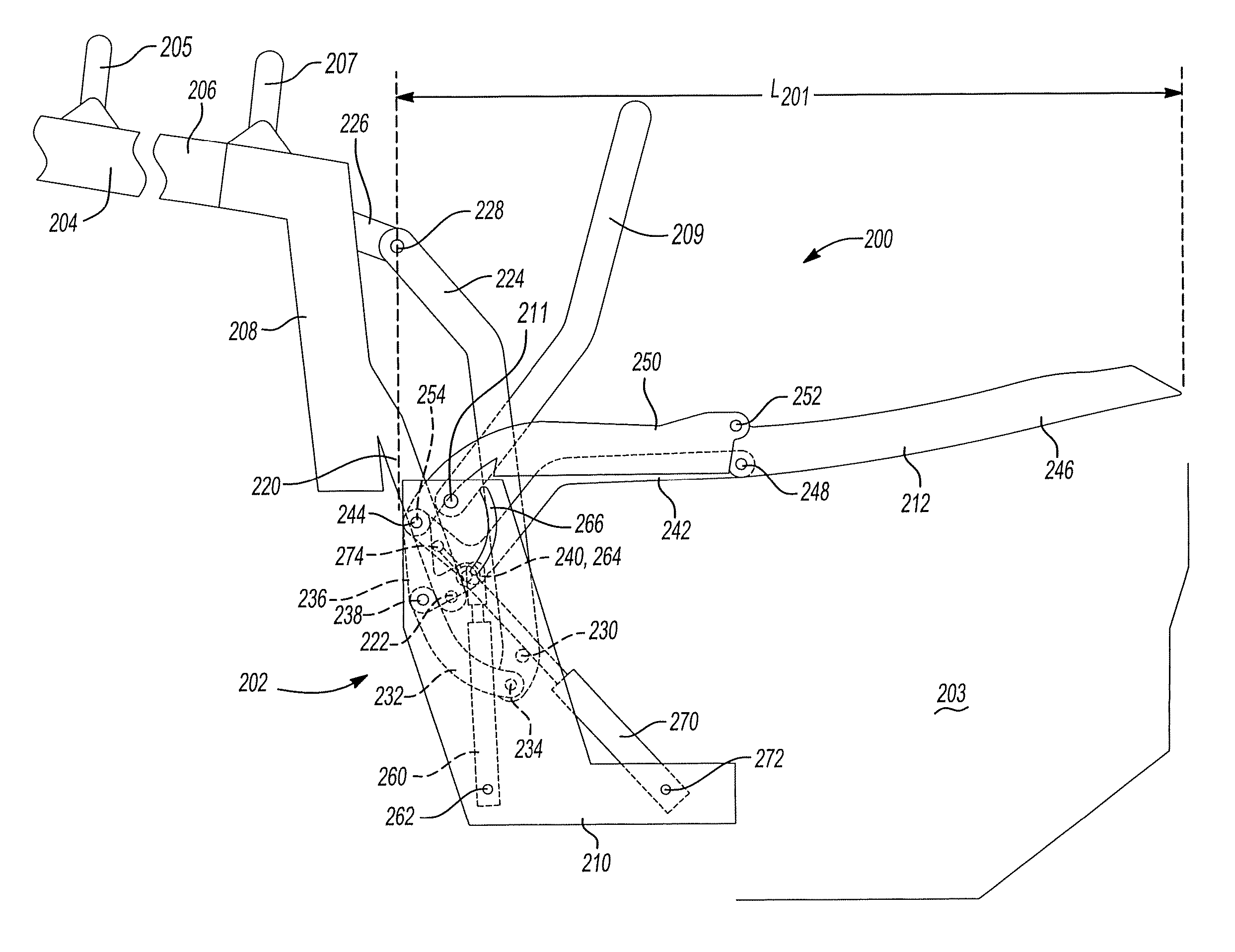
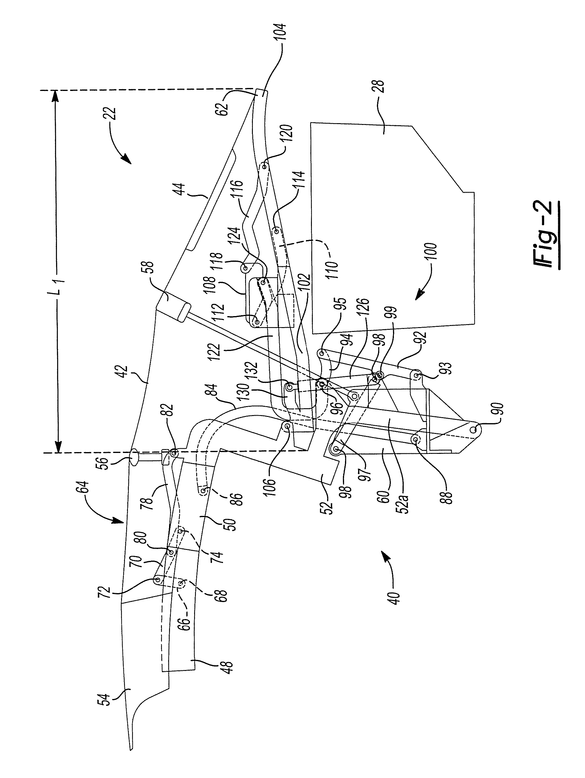
[0032]In the figures, the convertible roof and the associated top stack mechanism are shown symmetrical about a longitudinal, fore-and-aft center line (not shown) of the vehicle. The center line, thus, also serves as a longitudinal center line for the convertible roof and the top stack mechanism and its associated linkages and components. The top stack mechanism includes right and left roof linkages on the respective right and left sides of the vehicle. For brevity, at times only one side of the top stack mechanism and the convertible roof may be shown and / or discussed. However, it should be understood that the other side linkages are also provided as part of the top stack mechanism and the convertible roof and are mirrored images of the side depicted and / or discussed. Also, when using the terms “fore” and “aft,”“front” and “back,” and “forward” and...


PUM


Abstract

A convertible roof includes a segmented rearmost roof bow that has a length that can change during the retraction and extension process. The rearmost roof bow can be segmented such that the pieces can move relative to one another to shorten a length of the rearmost roof bow when being stowed. When in the fully raised and operative position, the sections of the segmented rearmost roof bow can be aligned and form a roof bow having an operative length. In the retracted state, the sections of the segmented rearmost roof bow can be moved relative to one another such that they are no longer aligned and have a length that is less than the operative length when aligned.

Description

CROSS-REFERENCE TO RELATED APPLICATIONS[0001]This application claims the benefit of U.S. Provisional Application No. 60 / 857,739, filed on Nov. 8, 2006. The disclosure of the above application is incorporated herein by reference.BACKGROUND AND SUMMARY OF THE INVENTION[0002]The present invention relates to convertible roofs and, more particularly, to convertible roofs with a shortening rearmost roof bow.[0003]Traditional soft-top convertible roofs for automotive vehicles typically employ three, four or five roof bows, having an inverted U-shape spanning transversely across the vehicle for supporting a vinyl, canvas or polyester fabric pliable roof cover. A number one roof bow is mounted to a pair of front roof rails and is typically latched to a stationary front header panel of the automotive vehicle body disposed above the front windshield. A number two roof bow is typically mounted to either the front roof rails or to a pair of center roof rails which are pivotally connected to the ...

Claims


Application Information

Patent Timeline
Patent Type & Authority Patents(United States)
IPC IPC(8): B60J7/10
CPCB60J7/1247B60J7/1265
Inventor GARSKA, BRADLEY R.DILLUVIO, CHRISTOPHER J.
Owner SPECIALTY VEHICLE ACQUISITION
Why Eureka
Try Eureka