
Method and apparatus for allocating bearer resources

a resource allocation and resource technology, applied in the field of bearer resource allocation process, can solve the problems of reducing the utilization ratio of system resources, increasing the processing delay of the system itself, and reducing the response speed of the system to the service, so as to reduce the waste of bearer resources, improve system utilization efficiency, and reduce time delay

Inactive Publication Date: 2015-08-25
ZTE CORP
View PDF49 Cites 2 Cited by
  • Summary
  • Abstract
  • Description
  • Claims
  • Application Information

AI Technical Summary

Benefits of technology

The present invention helps reduce waste of EPC bearer resources, decreases time delay, and improves system utilization efficiency, by implementing a reasonable allocation of bearer resources.

Problems solved by technology

Thus, when the number of bearers reaches the upper limit, initiation of new services will not be accepted, thereby reducing the utilization ratio of system resources.
Scheme 2: the EPC will firstly search for the bearer context whenever it receives the bearer resource allocation request, which inevitably increases the processing delay of the system itself, and decreases the response speed of the system to the service.

Method used


Image

  • Method and apparatus for allocating bearer resources
  • Method and apparatus for allocating bearer resources
  • Method and apparatus for allocating bearer resources

Examples


first embodiment

The First Embodiment

[0062]This embodiment introduces a preferred scheme of bearer resource allocation, where a bearer resource allocation apparatus is positioned in a PDN GW (i.e., the PDN GW can implement the function of bearer resource allocation) in an EPC. The specific process as shown in FIG. 3 comprises the following steps:

[0063]In S301, the PDN GW in the EPC obtains EPS bearer information of the currently activated EPS bearers and creates an EPS bearer information table, which includes IMSIs of all attached UEs, IDs of the activated bearers of the UEs, QoS class identifiers (QCIs) corresponding to the bearers, priorities and current bearer states.

[0064]The IDs of the activated bearers of the UEs and QCIs can be obtained from bearer context maintained locally by the PDN GW, and the priorities are obtained by querying from a standard QCI characteristic table (e.g., Table 1) pre-configured by an operator according to the QCIs of the bearers. The current bearer state may be deter...

second embodiment

The Second Embodiment

[0072]In order to improve the utilization ratio of bearer resources, this embodiment can be implemented by modifying step S303 in the first embodiment as follows. It should be noted that FIG. 4 mainly describes a flowchart of an operation procedure where no bearer corresponding to a QCI consistent with the QCI carried in the bearer resource allocation request message of the UE is found in the EPS bearer information table.

[0073]The specific modification steps include the following steps:

[0074]In S401, no bearer corresponding to the QCI consistent with the QCI carried in the bearer resource allocation request message of the UE is found in the EPS bearer information table.

[0075]In S402, the standard QCI characteristic table (e.g., Table 1) is searched according to the QCI carried in the bearer resource allocation request message of the UE to obtain the corresponding priority.

[0076]In S403, records of all bearers with priorities lower than the priority obtained in S...


PUM


Abstract

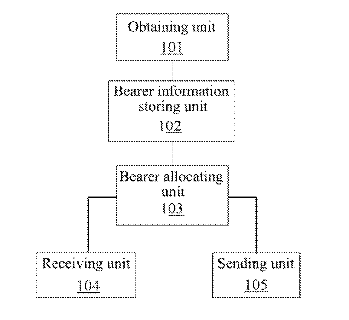
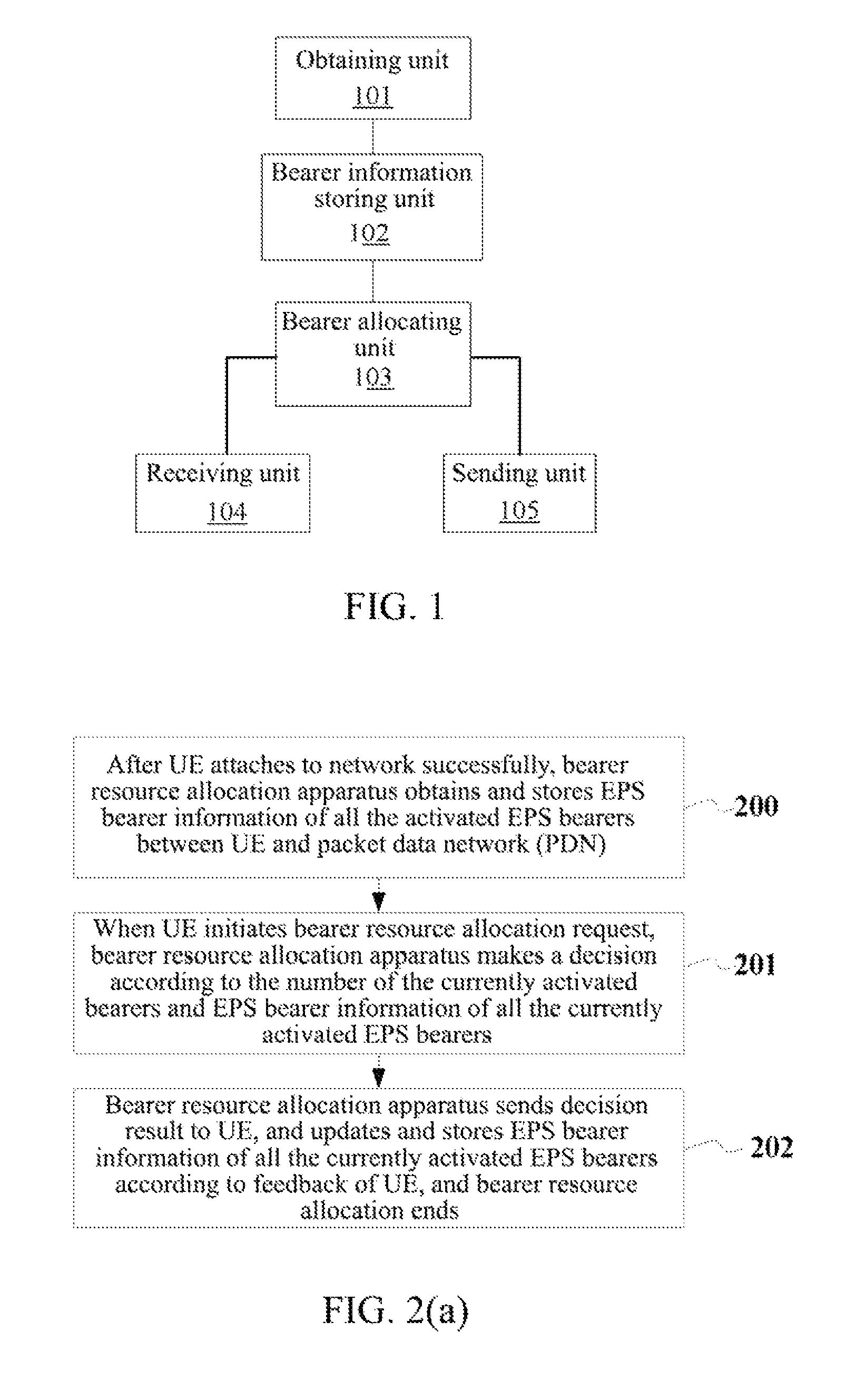
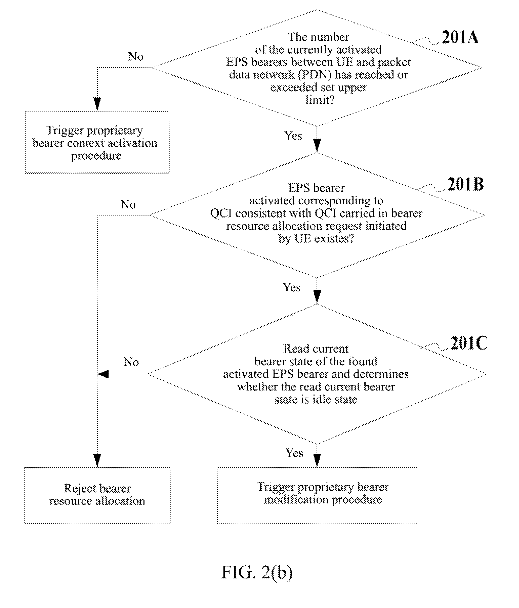
The invention discloses a method and apparatus for allocating bearer resources, and relates to LTE system in the communication field. The method comprises: when a network side receives a bearer resource allocation request initiated by a user, if the number of currently activated EPS bearers has reached or exceeded a set upper limit, the network side searching the currently activated EPS bearers according to a QCI carried in the bearer resource allocation request, and if an EPS bearer corresponding to a QCI consistent with the QCI carried in the bearer resource allocation request is found, performing a proprietary bearer modification operation on the found EPS bearer to respond to the bearer resource allocation request.

Description

TECHNICAL FIELD[0001]The present invention relates to a bearer resource allocation process in the LTE (Long Term Evolution) system in the communication field, and in particular, to a method and apparatus for allocating bearer resources.BACKGROUND ART[0002]The 3GPP (3rd Generation Partnership Projection) Evolved Packet System (EPS) consists of the Evolved UMTS Terrestrial Radio Access Network (EUTRAN) and Evolved Packet Core (EPC). The EPC, which consists of Mobility Management Entities (MMES), Serving gateways (GWs) and Packet Data Network GWs (PDN GWs), is mainly responsible for management of mobility, processing of Non-Access-Stratum, and EPS bearer resource control and other related works.[0003]EPS bearer is a logic aggregate of one or more service data streams, and is located between user equipment (UE) and PDN GW. When the UE does data services after attaching to the core network, it will obtain bearer resources required for the services by initiating a bearer resource allocati...

Claims


Application Information

Patent Timeline
Patent Type & Authority Patents(United States)
IPC IPC(8): H04W28/02H04W76/02H04W72/04H04W28/06H04W72/54
CPCH04W76/025H04W28/06H04W72/042H04W72/0413H04W72/0453H04W76/15H04W72/21H04W72/23
Inventor GUO, JING
Owner ZTE CORP
Learn More