Energy saving combustion device for burning refractory hazardous gas and method for operating the same

a technology of hazardous gas and combustion device, which is applied in the direction of combustion type, lighting and heating apparatus, incinerator apparatus, etc., can solve the problems affecting and affecting the health of human bodies, so as to improve the treatment efficiency of waste gases and reduce the effect of toxicity and explosion

Active Publication Date: 2017-04-13
KOREA INST OF ENERGY RES
View PDF3 Cites 1 Cited by
  • Summary
  • Abstract
  • Description
  • Claims
  • Application Information

AI Technical Summary

Benefits of technology

[0049]According to the present invention, the combustion device for burning refractory hazardous gases is configured to achieve high treatment efficiencies and high energy efficiencies and to allow waste gases to sufficiently reach a high temperature at which the waste gases are decomposed.
[0050]Further, the combustion device for burning refractory hazardous gases according to the present invention can perform combustion in the interiors of porous bodies, without having any additional device like a heat exchanger, so that heat recirculation can occur through the heat transfer of the conduction and radiation of the porous bodies, and further, the excess enthalpy combustion can be easily conducted at a high temperature.
[0051]Furthermore, the combustion device for burning refractory hazardous gases according to the present invention can mix the waste gases excessively diluted with inert gas with fuel and oxidizer, supply the mixed waste gases to the interiors of porous bodies, and burn the waste gases, so that the waste gases can be burned by very high temperature flames, which are not obtained in the typical combustion technologies, through the heat recirculation of the porous bodies, thus improving the treatment efficiencies of the waste gases, and also, the combustion device can treat the waste gases only with a relatively small quantity of fuel, thus improving the energy efficiencies.
[0052]Additionally, the combustion device for burning refractory hazardous gases according to the present invention can move any one of porous bides so as to effectively form flames in an initial step and to ensure a space for forming a flame surface, thus solving the problems that a long period of time is needed to stabilize the temperatures of flames and energy efficiencies are decreased when the flame surface is formed in the interiors of the porous bodies, and further, the combustion device of the present invention can ensure sufficient air for forming the flame surface, thus effectively forming the flame surface within a short period of time.
[0053]Moreover, the combustion device of the present invention can move any one of porous bides so as to constantly maintain the temperature of a flame surface if the temperature of the flame surface is decreased to reduce the efficiency of the combustion device, while driven, thus increasing the space of the flame surface to ensure sufficient air for forming the flame surface, and further, the combustion device of the present invention can constantly maintain the temperature of the flame surface to increase the efficiency of the combustion device.
[0054]The present invention may be modified in various ways and may have several exemplary embodiments. Specific exemplary embodiments of the present invention are illustrated in the drawings and described in detail in the detailed description. However, this does not limit the invention within specific embodiments and it should be understood that the invention covers all the modifications, equivalents, and replacements within the idea and technical scope of the invention.

Problems solved by technology

Generally, various kinds of reaction gases used to form a thin film on a wafer or to etch the thin film in the semiconductor manufacturing process have the properties of explosion, extremely high toxicity and suffocating, and accordingly, if they are emitted to the air with no treatment, they are harmful to the human bodies and cause global warming and environmental pollution.
The PFCs, SF6, and NF3 are decomposed to the bonded forms to fluorine and exhausted to the forms of hydrofluoric acid and fluorine, and in this case, they have the properties of extremely high toxicity and explosion, so that they have cleaning reaction with water and are then exhausted.
Firstly, the burning treatment is conducted by using fossil fuels (for example, LNG) and has some disadvantages of low treatment efficiencies of PFCs, bad flame stability (burning process) and the decrement of products (for example, NOx and CO) after burning.
Secondly, the catalytic decomposition treatment has some problems of catalyst poisoning by high density acid gas (HF, HCL, etc.), increment of operating cost due to short catalyst exchange period, and pressure rise of a system caused by the introduction of particles.
Lastly, the thermal plasma burning and electrolysis treatments make use of electricity as an energy source, and accordingly, they need very high power energy when compared with the capacity treated.
The thermal plasma burning treatment causes frequent exchange due to the non-existence of durable torch materials, generates a large quantity of NOx, and needs the bulkiness of incidental equipment (transformer) according to power increment upon high capacity treatment.
Further, the electrolysis treatment has a short exchange period due to the durability problem (electric heater etching) of a heating element and is hard to conduct heating at a high temperature of more than 1600° C.
In this case, however, even the inert gas whose treatment is unnecessary should be heated, thus undesirably making the treatment efficiencies and energy efficiencies substantially lowered.
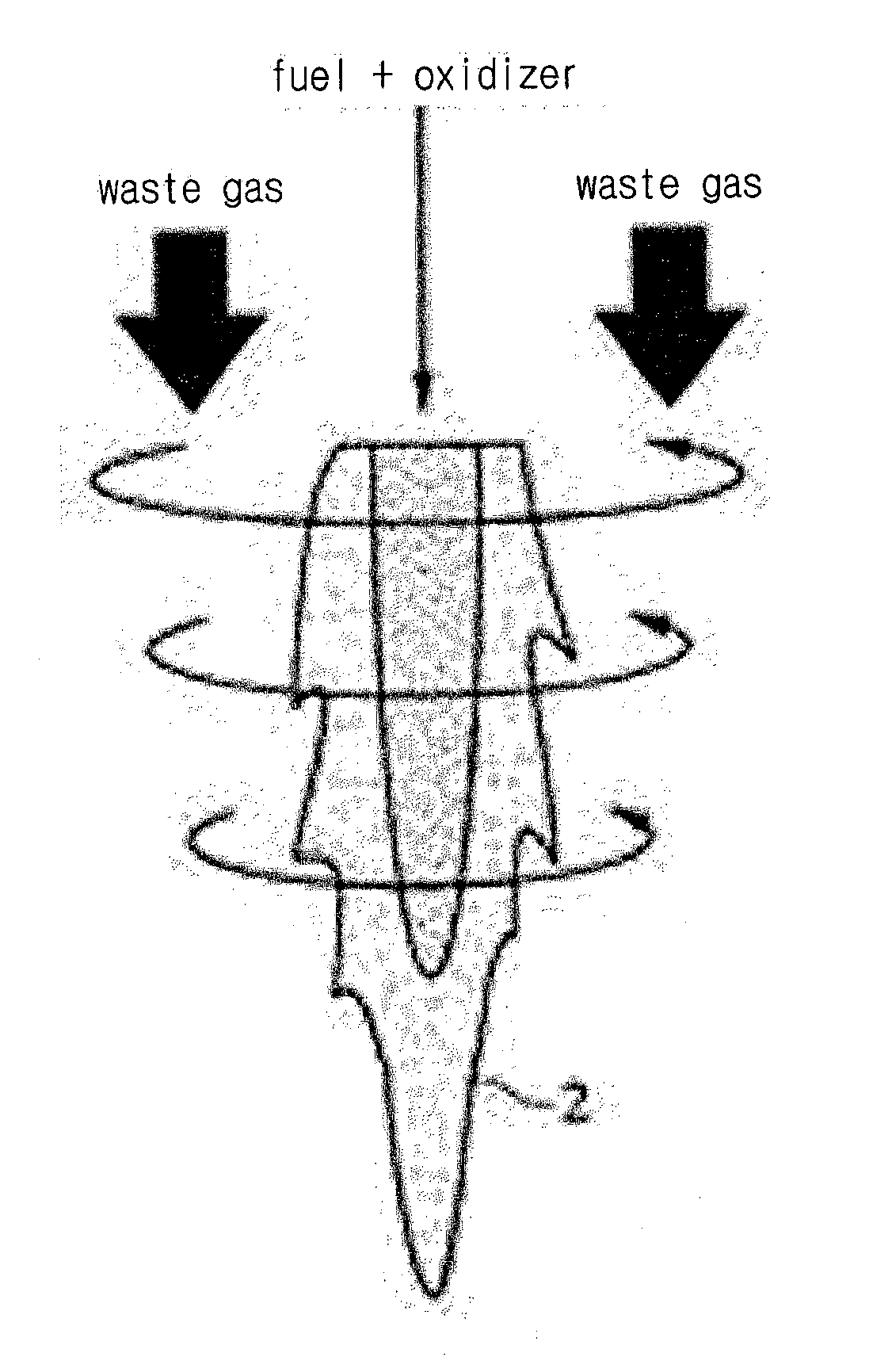
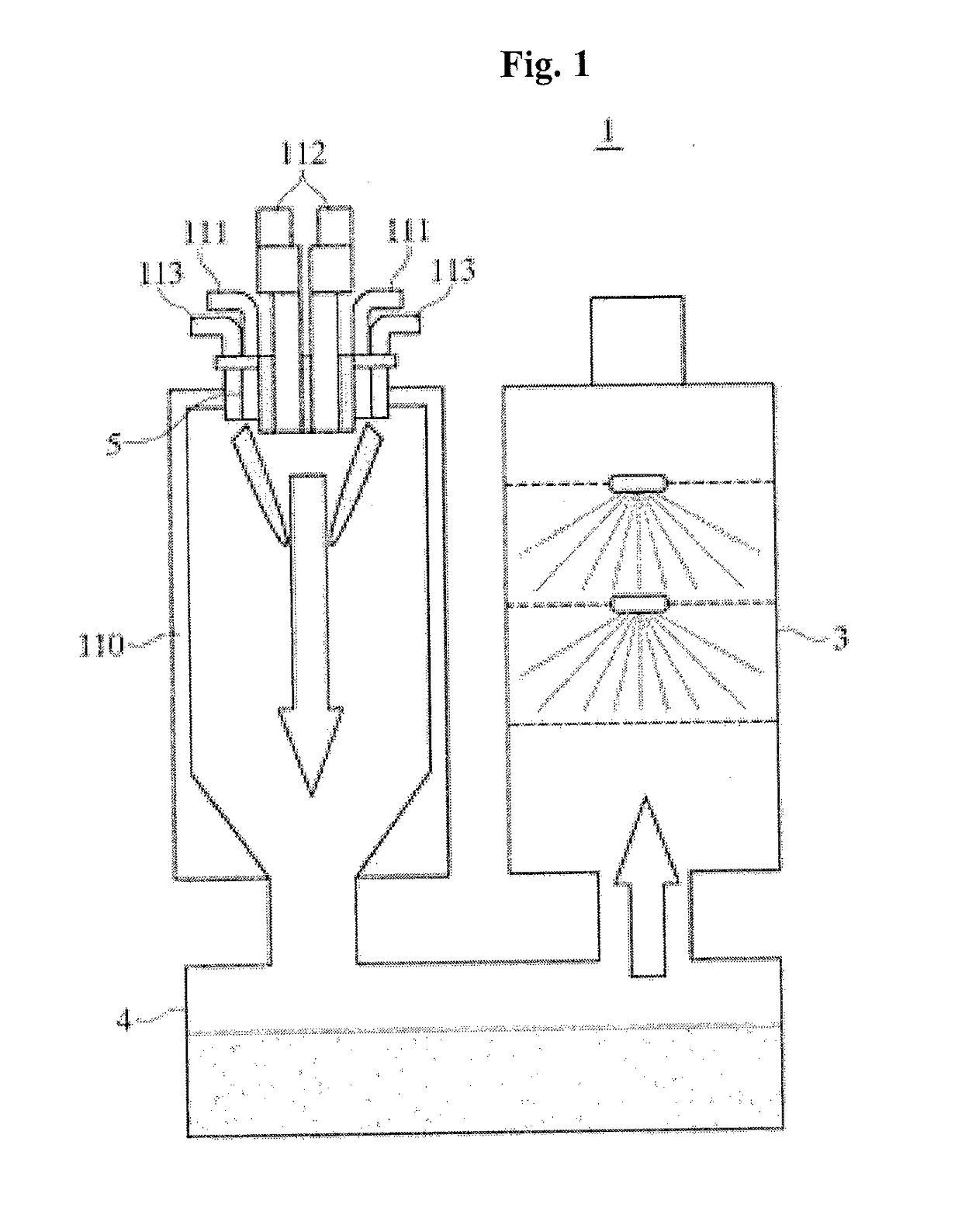
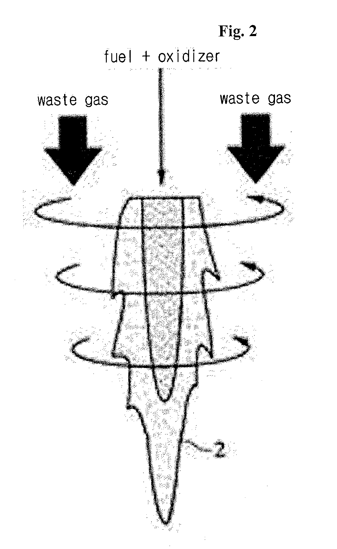
Even if the swirls are sufficiently generated in FIG. 2, however, it is difficult that the combustion gases and the waste gases are sufficiently mixed with each other in the combustion device 110 whose size is restricted.
Generally, flow rates of waste gases are higher than that of combustion gases, so that large momentums of the waste gases make the flames unstable or even extinguished, thus undesirably decreasing the treatment efficiencies.
In this case, however, energy efficiencies become low.
Further, as shown in FIGS. 3 and 4, the flames 2 having the shapes of inverted slant cones become not closed on the slant surfaces thereof, but become open by means of the momentums of the waste gases, so that the waste gases are escaped from the high temperature flames, thus undesirably decreasing the decomposition efficiencies.

Method used


Image

  • Energy saving combustion device for burning refractory hazardous gas and method for operating the same
  • Energy saving combustion device for burning refractory hazardous gas and method for operating the same
  • Energy saving combustion device for burning refractory hazardous gas and method for operating the same

Examples


Embodiment Construction

[0063]Hereinafter, the technological configurations of a combustion device for burning refractory hazardous gases according to the present invention will be in detail described with reference to drawings. If it is determined that the detailed explanation on the well known technology related to the present invention makes the scope of the present invention not clear, the explanation will be avoided for the brevity of the description.

[0064]In the description, also, the corresponding parts in the embodiments of the present invention are indicated by corresponding reference numerals and the repeated explanation on the corresponding parts will be avoided. Further, the term ‘coupled’ or ‘connected’, as used herein, is defined as connected, although not necessarily directly, and not necessarily mechanically. To the contrarily, the term ‘directly coupled’ or ‘directly connected’, as used herein, is defined as connected without having any component disposed therebetween.

[0065]Hereinafter, an...


PUM


Abstract

The present invention relates to a combustion device 100 for burning refractory hazardous gases and a burning method for the combustion device. More particularly, the combustion device 110 for burning refractory hazardous gases, which is provided in a scrubber system 1 for burning waste gases, the combustion device 110 includes: a first porous body 141; a second porous body 142; and an igniter for forming a flame surface 143 at the interior of the combustion device 110, wherein the flame surface 143 formed by the igniter is located between the first porous body 141 and the second porous body 142, and so as to form the flame surface 143, at least one of the first porous body 141 and the second porous body 142 is moved to conduct excess enthalpy combustion.

Description

TECHNICAL FIELD[0001]The present invention relates to a combustion device for burning refractory hazardous gases and a burning method using the combustion device. More particularly, the present invention relates to a combustion device for burning refractory hazardous gases that is provided in a system for burning refractory hazardous gases (a group of perfluorocarbons PFCs, such as CF4, C2F6, C2F4 and SF6, and NF3) used and discharged in semiconductor and display manufacturing processes and other various refractory hazardous gases discharged in chemical processes.BACKGROUND ART[0002]PFCs gases, which are much used in semiconductor and display manufacturing processes, are greenhouse gases causing global warming and have a higher global warming potential by several thousands to tens of thousands of times than CO2. Accordingly, the PFCs gases should be emitted to the air through treatment equipment.[0003]Generally, various kinds of reaction gases used to form a thin film on a wafer or ...

Claims


Application Information

Patent Timeline
Patent Type & Authority Applications(United States)
IPC IPC(8): F23G7/06
CPCF23G7/06F23G7/065F23G2201/70F23G2207/101F23J15/04Y02E20/34F23G5/50F23G2209/14F23L7/007
Inventor LEE, DAE KEUNKIM, SEUNG-GONNOH, DONG-SOONKO, CHANG-BOGGUAHK, YOUNG-TAE
Owner KOREA INST OF ENERGY RES
Why Eureka
Try Eureka