Filling device for filling containers

a filling device and container technology, applied in the direction of packaging, transportation and packaging, liquid handling, etc., can solve the problems of insufficient mixing and difficulty in realizing

Active Publication Date: 2015-09-01
KRONES AG
View PDF34 Cites 4 Cited by
  • Summary
  • Abstract
  • Description
  • Claims
  • Application Information

AI Technical Summary

Benefits of technology

[0023]Advantageously, the valve body is adjacent to the mixing chamber. This means that, for example, during a filling process, the two liquids are initially mixed together in the mixing chamber and subsequently the mixture is discharged from the filling device by opening the valve body. In this way, also any splashing that might be caused by pieces of fruit may be prevented.
[0025]In a further advantageous embodiment, a bellow for sealing the actuation element is provided on the inside of the first liquid channel. Since this actuation element—as was explained above—is advantageously guided within the liquid channel, a sealing off of the actuation element against the liquid surrounding it may be achieved by said bellow. This bellow allows a movement of the actuation element and prevents at the same time that the actuation element comes into contact with the liquid.
[0026]In a further advantageous embodiment, a centring element, which is movable relative to the first liquid channel, for centring a position of the valve body is provided inside the second liquid channel. This centring element is thus guided by the liquid channel or the internal wall thereof, so that the valve body may be moved at all times to an exact position relative to the filling device in its longitudinal direction. In this way, a proper closing of the valve of the filling device is made possible.
[0027]In a further advantageous embodiment, the first liquid channel is shorter than the second liquid channel in a longitudinal direction of the filling device. Particularly preferably here the outer channel is also shorter than the inner channel and is shorter than the inner channel particularly towards the top, i.e. away from the container. Advantageously, therefore, the port which leads to the outer or second channel is at a lower level than the port leading to the inner channel or the first channel. As mentioned above, the first channel is advantageously used for filling in a main product and the second channel for filling in the second liquid, which may in particular be a pulp. Here, no complex feed-through of a product line through the wall of an outer channel into an inner channel is necessary, so that the construction may be simple in design, cost effective in manufacturing and have low maintenance requirements.

Problems solved by technology

In particular, if one of the components is a component including fruit pieces or the like, then this may sometimes be difficult to realise, since the respective valves may cause these liquids to splash about.
Due to this arrangement of the valve, however, an inadequate mixing of the two liquids to be mixed may occur, and the obstruction of the outlet of the mixed liquid from the filling device is connected with problems, if said second liquid contains pieces of fruit or the like.

Method used


Image

  • Filling device for filling containers
  • Filling device for filling containers
  • Filling device for filling containers

Examples


Embodiment Construction

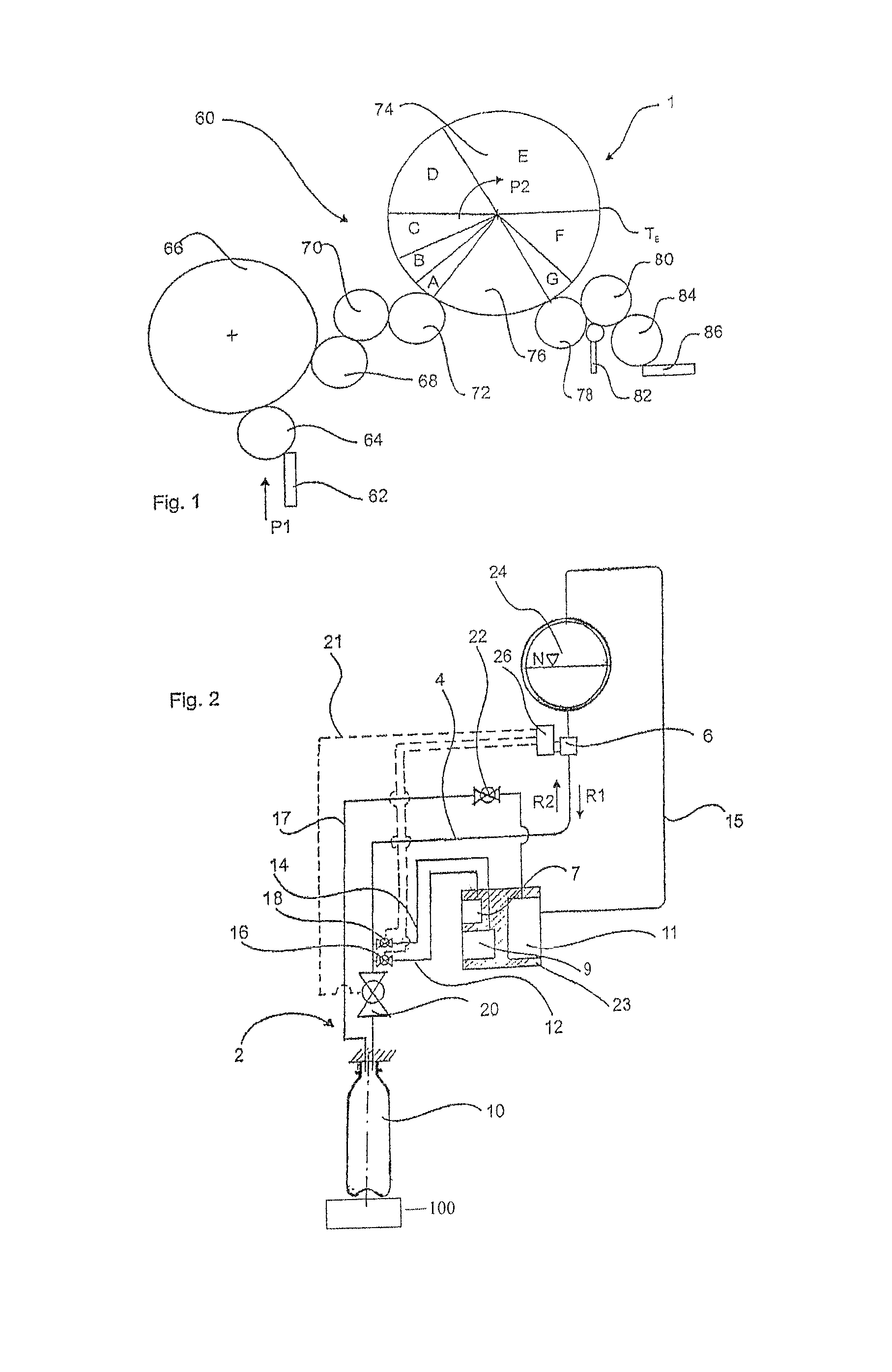
[0039]Reference numeral 68 relates to an out-feed star wheel of the rinsing device 66 which takes over the rinsed containers and passes them on via a transfer star wheel 70 and a filler inflow star wheel 72 to an apparatus 1 for bottling beverages. In this apparatus 1, two-component beverages are bottled. Reference letters A to G identify different method steps carried out when bottling the beverages. Thus, in a step A, the container is pressed against a filling device, and in a step B, the container is preloaded or a gaseous medium such as for example carbon dioxide is applied to it. In a step C, an initial amount of a clear main product is filled into the container, such as for example a carbonated beverage. In a step D, a secondary product may be supplied or a secondary product plug may be filled into the main product. In zone E, a post-filling of the main product takes place. Reference letter TE identifies the end of the filling process of the beverage into the container.

[0040]I...


PUM

PropertyMeasurementUnit
angleaaaaaaaaaa
lengthaaaaaaaaaa
volumeaaaaaaaaaa

Abstract

A filling device for filling containers with a liquid has a first port for supplying a first liquid to the filling device, and a second port spaced from the first port for supplying a second liquid to the filling device. A mixing chamber within the filling device includes a first liquid channel which guides the first liquid from the first port to the mixing chamber, and a second liquid channel which guides the second liquid from the second port to the mixing chamber, wherein the first liquid channel and the second liquid channel guide the first liquid and the second liquid separately from one another. A valve body controls discharge of the liquids from the filling device through an outlet to the container. The valve body is disposed at least partially between the mixing chamber and the outlet.

Description

CROSS REFERENCE TO RELATED APPLICATION[0001]This application is a divisional of pending U.S. application Ser. No. 12 / 833,729, filed Jul. 9, 2010, now U.S. Pat. No. 8,800,610. This application also claims priority from German Patent Application Serial No. 10 2009 032 795.9, filed Jul. 10, 2009, the contents of which are incorporated herein in their entirety.BACKGROUND OF THE INVENTION[0002]The present invention relates to a filling device for filling containers and in particular for filling containers with multi-component beverages. Such filling devices are known from the prior art and are used, for example, for bottling still and carbonated beverages, to which syrups or liquids containing fibres or solids are added. It is to be noted, however, that the filling device described may also be suitable for bottling other liquids such as, for example, oils, milk, juices, liquid refreshments.[0003]In the case of such filling devices, usually several components of the substance to be bottle...

Claims


Application Information

Patent Timeline
Patent Type & Authority Patents(United States)
IPC IPC(8): B67C3/02B01F3/04B67C3/20B67C3/26
CPCB01F3/04794B67C3/02B67C3/20B67C3/208B67C3/26B01F2003/049B01F23/2361B01F23/237621
Inventor MEINZINGER, RUPERT
Owner KRONES AG
Why Eureka
Try Eureka