Monolithic, galleryless piston and method of construction thereof

a galleryless, monolithic technology, applied in the direction of machines/engines, manufacturing tools, mechanical apparatus, etc., can solve the problems of reducing the overall piston size and mass, limiting the degree, and particularly troublesome, so as to reduce the cost of piston manufacture, increase compression load, and increase strength and durability

Active Publication Date: 2015-05-07
TENNECO
View PDF3 Cites 32 Cited by
  • Summary
  • Abstract
  • Description
  • Claims
  • Application Information

AI Technical Summary

Benefits of technology

[0007]A piston constructed in accordance with this invention is constructed of a monolithic piece of steel, thereby providing the piston with enhanced strength and durability to withstand increased compression loads and temperatures within a cylinder bore, such as those loads and temperatures seen in modern high performance engines. Further, due to the novel single piece configuration of the piston, the costs associated with the manufacture of the piston are reduced in that the typical processes used to join p

Problems solved by technology

Accordingly, although desirable to increase the compression load and operation temperature within the combustion chamber, achieving this goal comes with a tradeoff in that these desirable “increases” limit the degree to which the piston compression height, and thus, overall piston size and mass can be decreased.
This is particularly troublesome with typical piston constructions having a closed or partially closed cooling gallery considered necessary to reduce the operating temperature of the piston.
Fu

Method used


Image

  • Monolithic, galleryless piston and method of construction thereof
  • Monolithic, galleryless piston and method of construction thereof
  • Monolithic, galleryless piston and method of construction thereof

Examples


Embodiment Construction

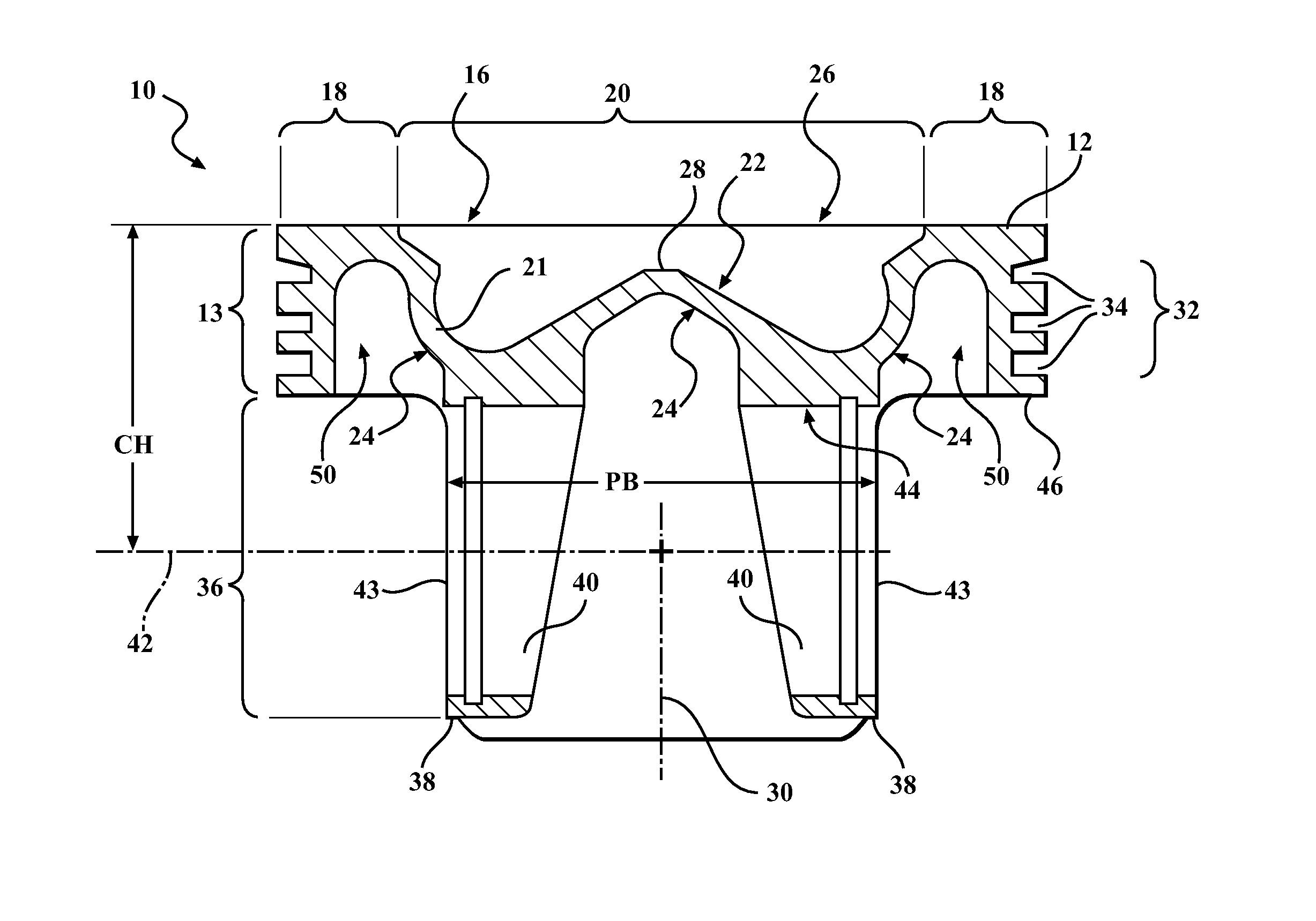
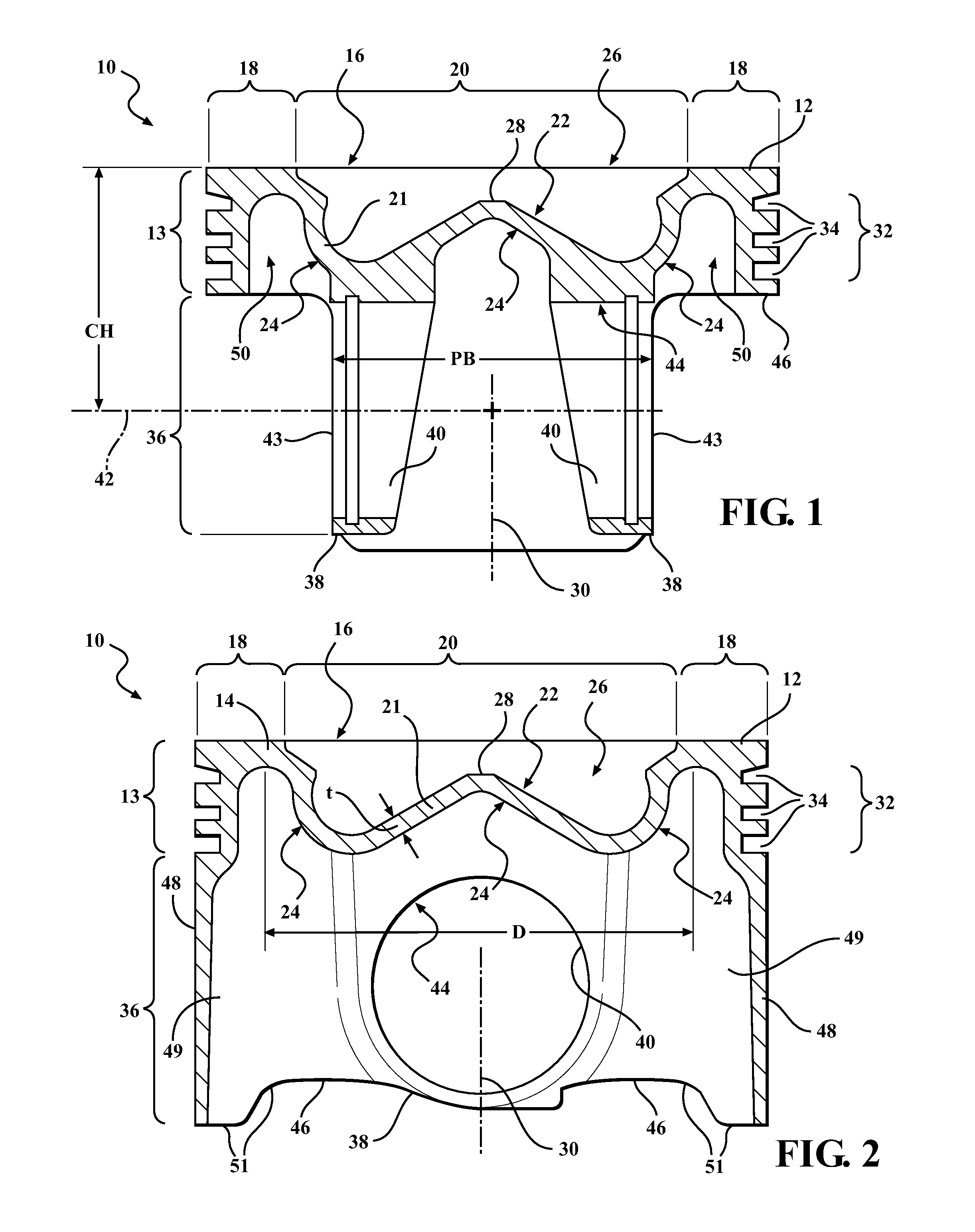
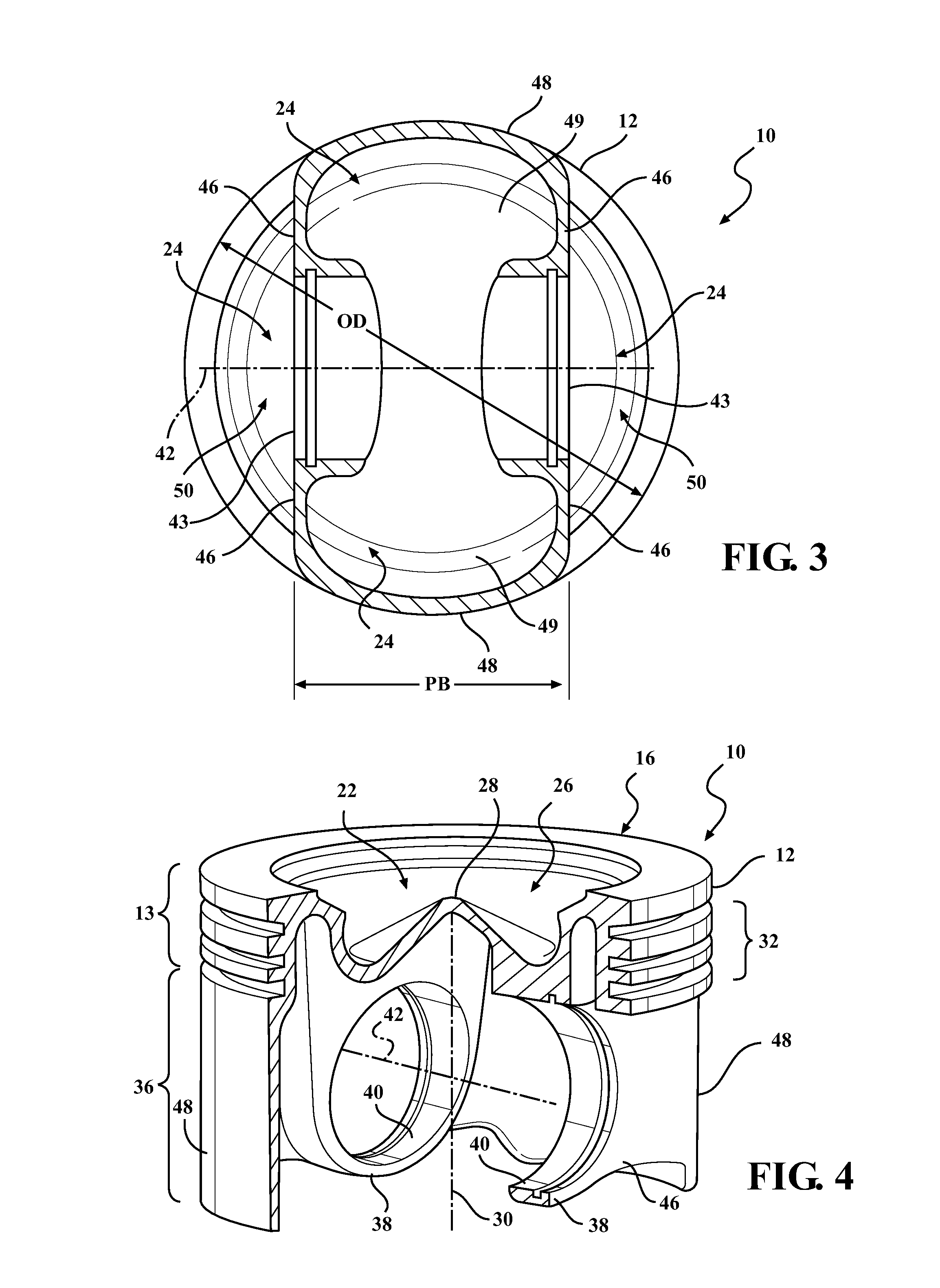
[0048]Referring in more detail to the drawings, FIGS. 1-4 illustrate views of a piston 10 constructed in accordance with one presently preferred embodiment of the invention for reciprocating movement in a cylinder bore or chamber (not shown) of an internal combustion engine, such as a modern, compact, high performance vehicle engine, for example. The piston 10 is constructed having a monolithic body 12 formed from a single piece of material, such as via machining, forging or casting, with possible finish machining performed thereafter, if desired, to complete construction. Accordingly, the piston 10 does not have a plurality of parts joined together, such as upper and lower parts joined to one another, which is commonplace with pistons having enclosed or partially enclosed cooling galleries bounded or partially bounded by a cooling gallery floor. To the contrary, the piston 10 is “galleryless” in that it does not have a cooling gallery floor or other features bounding or partially b...


PUM

PropertyMeasurementUnit
Fractionaaaaaaaaaa
Fractionaaaaaaaaaa
Fractionaaaaaaaaaa

Abstract

A galleryless piston for an internal combustion engine and method of construction thereof are provided. The piston has a monolithic piston body extending along a central longitudinal axis. The piston body has an upper wall forming an upper combustion surface with first and second portions, with the first portion extending annularly along an outer periphery of the upper wall and the second portion forming a combustion bowl. The upper wall has an undercrown surface on an underside of the combustion bowl directly opposite the second portion of the upper combustion surface. The undercrown surface has an openly exposed 2-dimensional surface area, as viewed looking along the central longitudinal axis, between about 35-60 percent of an area defined by a maximum outer diameter of the piston body, thereby providing an expansive area against which oil being splashed or sprayed can freely contact to cool the piston.

Description

CROSS-REFERENCE TO RELATED APPLICATION[0001]This application claims the benefit of U.S. Provisional Application Ser. No. 61 / 901,287, filed Nov. 7, 2013, and the benefit of U.S. Provisional Application Ser. No. 62 / 011,876, filed Jun. 13, 2013, both of which are incorporated herein, by reference, in their entirety.BACKGROUND OF THE INVENTION[0002]1. Technical Field[0003]This invention relates generally to internal combustion engines, and more particularly to pistons therefor.[0004]2. Related Art[0005]Engine manufacturers are encountering increasing demands to improve engine efficiencies and performance, including, but not limited to, improving fuel economy, reducing oil consumption, improving fuel systems, increasing compression loads and operating temperature within the cylinder bores, reducing heat loss through the piston, improving lubrication of component parts, decreasing engine weight and making engines more compact, while at the same time decreasing the costs associated with ma...

Claims


Application Information

Patent Timeline
IPC IPC(8): F02F3/00B23P15/10
CPCF02F3/0092F02F2003/0007B23P15/10F02F3/00Y10T29/49265F02F3/0069F02F3/16
Inventor RIFFE, JEFFWEINENGER, MICHAEL
Owner TENNECO
Why Eureka
Try Eureka