Filling device for filling containers

a filling device and container technology, applied in the directions of transportation and packaging, liquid handling, packaging goods, etc., can solve the problems of insufficient mixing and difficulty in realizing

Inactive Publication Date: 2014-08-12
KRONES AG
View PDF23 Cites 6 Cited by
  • Summary
  • Abstract
  • Description
  • Claims
  • Application Information

AI Technical Summary

Benefits of technology

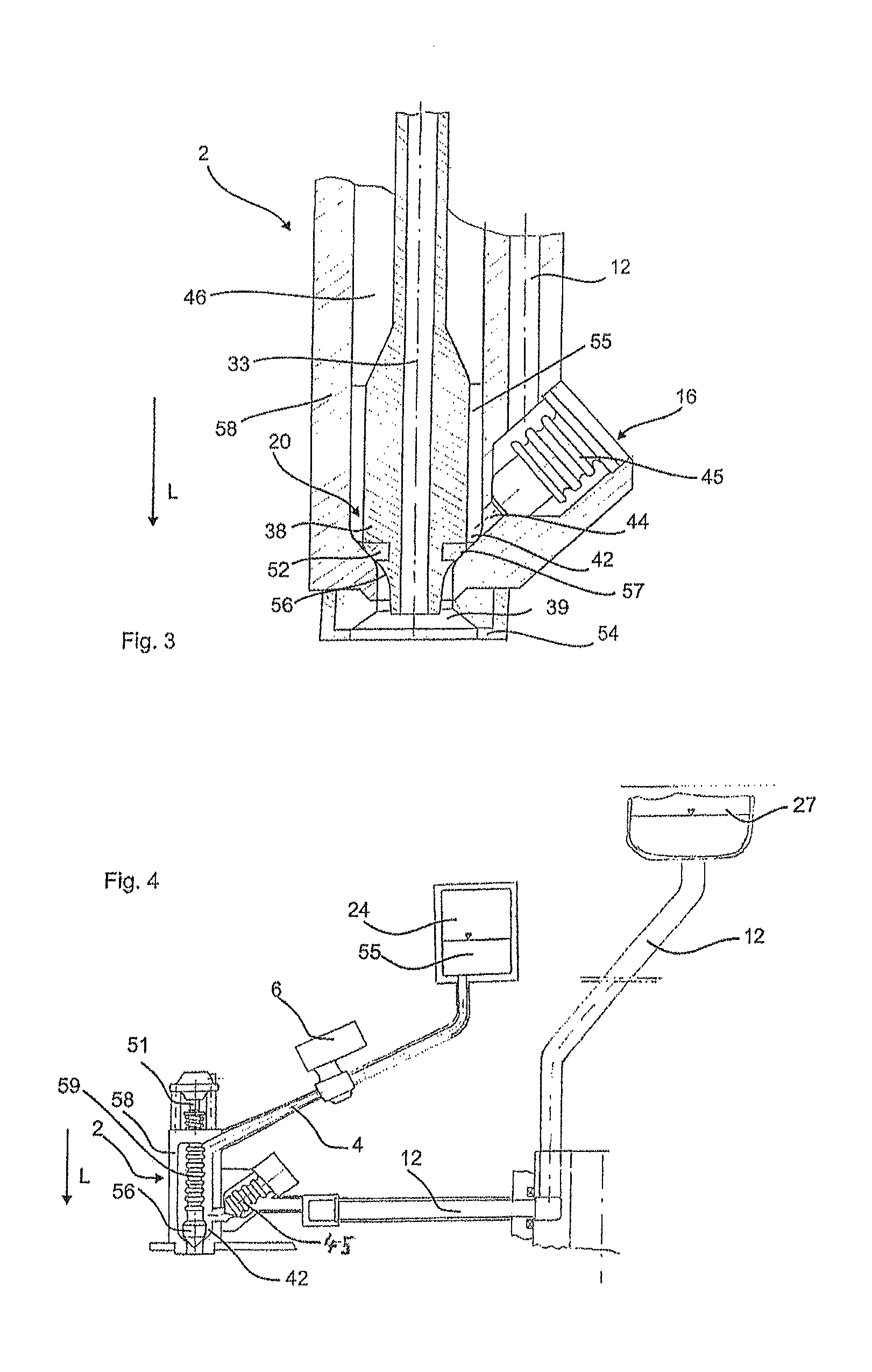
[0028]In a further advantageous embodiment, in at least one of the liquid lines and preferably in exactly one of the liquid lines, a flow measuring device is provided, which determines the quantity of liquid passing through the flow measuring device in two flow directions which are opposite to one another. Therefore, contrary to the prior art, it is suggested that the flow measuring devices can also determine the flow rate in both flow directions. In this way, the system may be able to work with just one flow measuring device, since for example when feeding in the second liquid, the first liquid will be pushed back by a certain volume and the flow measuring device can detect this displacemen

Problems solved by technology

In particular, if one of the components is a component including fruit pieces or the like, then this may sometimes be difficult to realise, since the respective valves may cause these liquids to splash about.
Due to this arrangement of the va

Method used


Image

  • Filling device for filling containers
  • Filling device for filling containers
  • Filling device for filling containers

Examples


Embodiment Construction

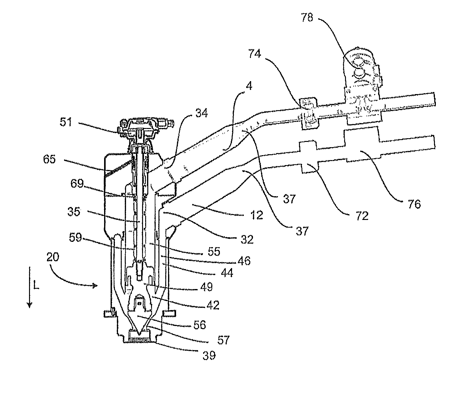
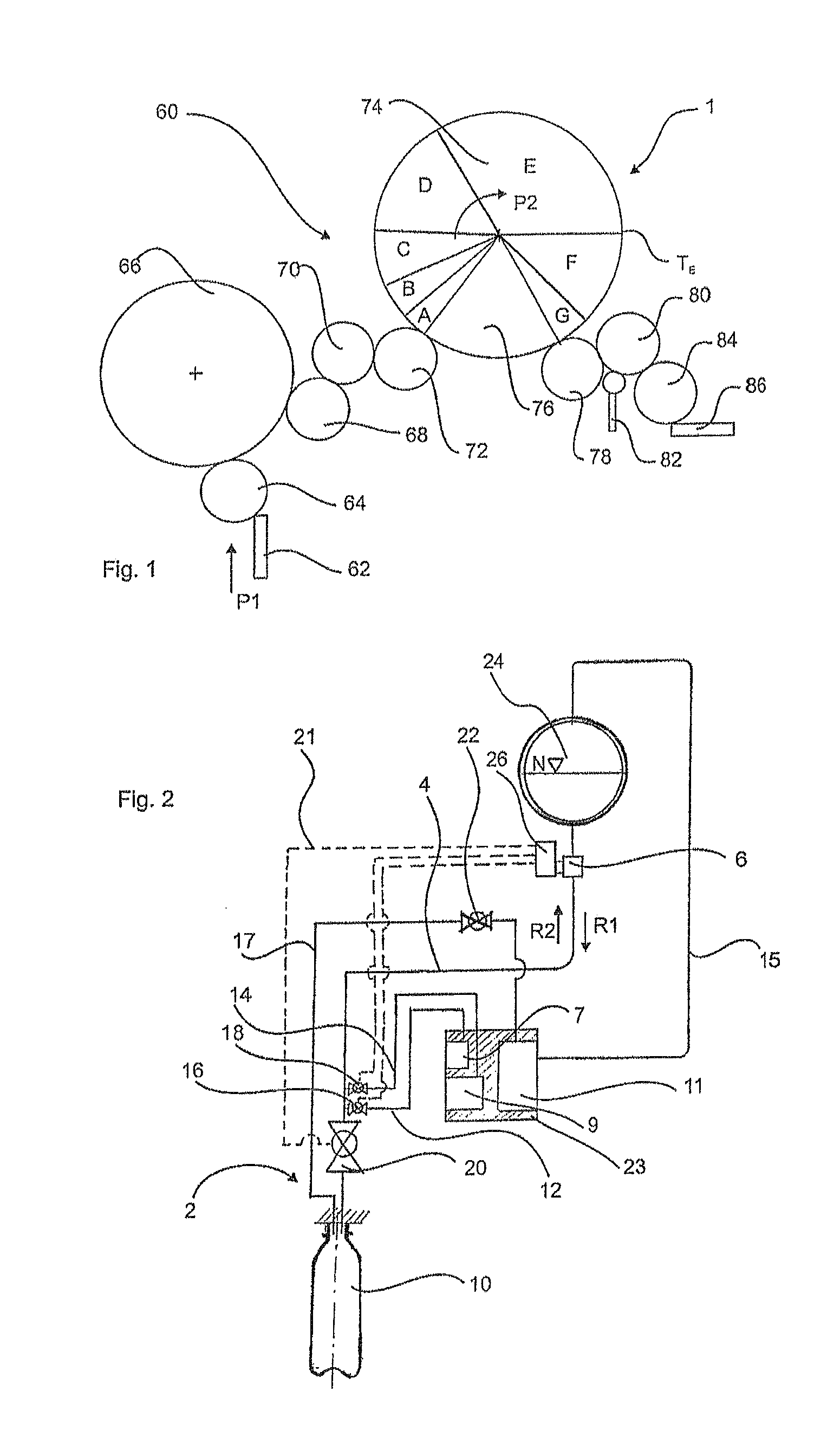
[0038]Reference numeral 68 relates to an out-feed star wheel of the rinsing device 66 which takes over the rinsed containers and passes them on via a transfer star wheel 70 and a filler inflow star wheel 72 to an apparatus 1 for bottling beverages. In this apparatus 1, two-component beverages are bottled. Reference letters A to G identify different method steps carried out when bottling the beverages. Thus, in a step A, the container is pressed against a filling device, and in a step B, the container is preloaded or a gaseous medium such as for example carbon dioxide is applied to it. In a step C, an initial amount of a clear main product is filled into the container, such as for example a carbonated beverage. In a step D, a secondary product may be supplied or a secondary product plug may be filled into the main, product. In zone E, a post-filling of the main product takes place. Reference letter TE identifies the end of the filling process of the beverage into the container.

[0039]...


PUM

PropertyMeasurementUnit
Angleaaaaaaaaaa
Flow rateaaaaaaaaaa

Abstract

A filling device for filling containers with a liquid has a first port for supplying a first liquid to the filling device, a second port spaced from the first port for supplying a second liquid to the filling device A mixing chamber within the filling device includes a first liquid channel which guides the first liquid from the first port to the mixing chamber, and a second liquid channel which guides the second liquid from the second port to the mixing chamber, wherein the first liquid channel and the second liquid channel guide the first liquid and the second liquid separately from one another A valve body controls discharge of the liquids from the filling device through an outlet to the container. The valve body is disposed at least partially between the mixing chamber and the outlet.

Description

BACKGROUND OF THE INVENTION[0001]The present invention relates to a filling device for filling containers and in particular for filling containers with multi-component beverages. Such filling devices are known from the prior art and are used, for example, for bottling still and carbonated beverages, to which syrups or liquids containing fibres or solids are added. It is to be noted, however, that the filling device described may also be suitable for bottling other liquids such as, for example, oils, milk, juices, liquid refreshments.[0002]In the case of such filling devices, usually several components of the substance to be bottled are added and these are filled into the container to be filled via a filling valve. In particular, if one of the components is a component including fruit pieces or the like, then this may sometimes be difficult to realise, since the respective valves may cause these liquids to splash about.[0003]The present invention is therefore based on the object of p...

Claims


Application Information

Patent Timeline
IPC IPC(8): B65B3/04
CPCB67C3/20B67C3/02B01F2003/049B67C3/208B01F3/04794B67C3/26B01F23/2361B01F23/237621
Inventor MEINZINGER, RUPERT
Owner KRONES AG
Why Eureka
Try Eureka