
System and method for designating a target for a remote aerial vehicle

Active Publication Date: 2015-09-01
THE BOEING CO
View PDF6 Cites 23 Cited by
  • Summary
  • Abstract
  • Description
  • Claims
  • Application Information

AI Technical Summary

Benefits of technology

The invention provides a system and method for designating a target for an airborne missile that eliminates the time delay between designation of the target and the response of the sensor. This improves the overall effectiveness and user-friendlininess of the missile control. The operator can select as the target a feature other than the centroid of a defined area of the image of the target. The position of the missile at the time the video image is generated is recalled from the flight information stored in the guidance and navigation computer, and the three-dimensional coordinates of the target are estimated from this position. The estimated coordinates of the target are used to issue new pointing commands to the imaging sensor. This results in a faster and easier to operate system, and less training of the operator is required than conventional systems and methods. The invention also provides a cost-effective and efficient solution, and is applicable to a data link with low bandwidth frequency relay, such as a satellite.

Problems solved by technology

Although MITL control has been used to successfully designate targets in various missile systems, conventional MITL control methods suffer from a number of deficiencies.
Individually, and as a whole, these deficiencies reduce the overall effectiveness and user-friendliness of the missile system.
Most importantly, the inherent time delays in the data link between the missile and the control center may cause the MITL control loop to become unstable.
When this happens, the sensor may overshoot the target, resulting in a pointing error.
As a result, the control loop becomes unstable.
Even if the inherent time delays do not cause the control loop to become completely unstable, their effect is to destabilize the target designation process, and thus, they reduce the overall effectiveness of the MITL missile system.
Although other guidance trackers define the image of the target differently, they often share the same characteristic error.
In many cases, designating a desired target within the defined area of the target image is further complicated by characteristics of the target itself, the weather, and other uncontrollable variables.
Another problem inherent with conventional systems for MITL control is that the video images provided to the operator are generally not stable.

Method used


Image

  • System and method for designating a target for a remote aerial vehicle
  • System and method for designating a target for a remote aerial vehicle
  • System and method for designating a target for a remote aerial vehicle

Examples


Embodiment Construction

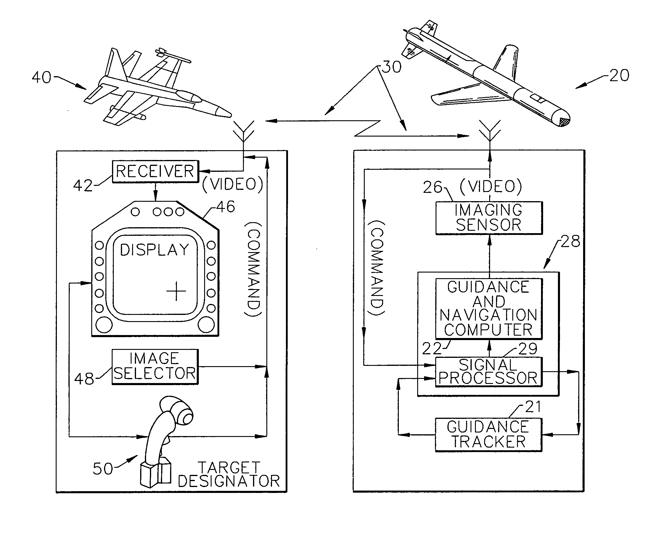
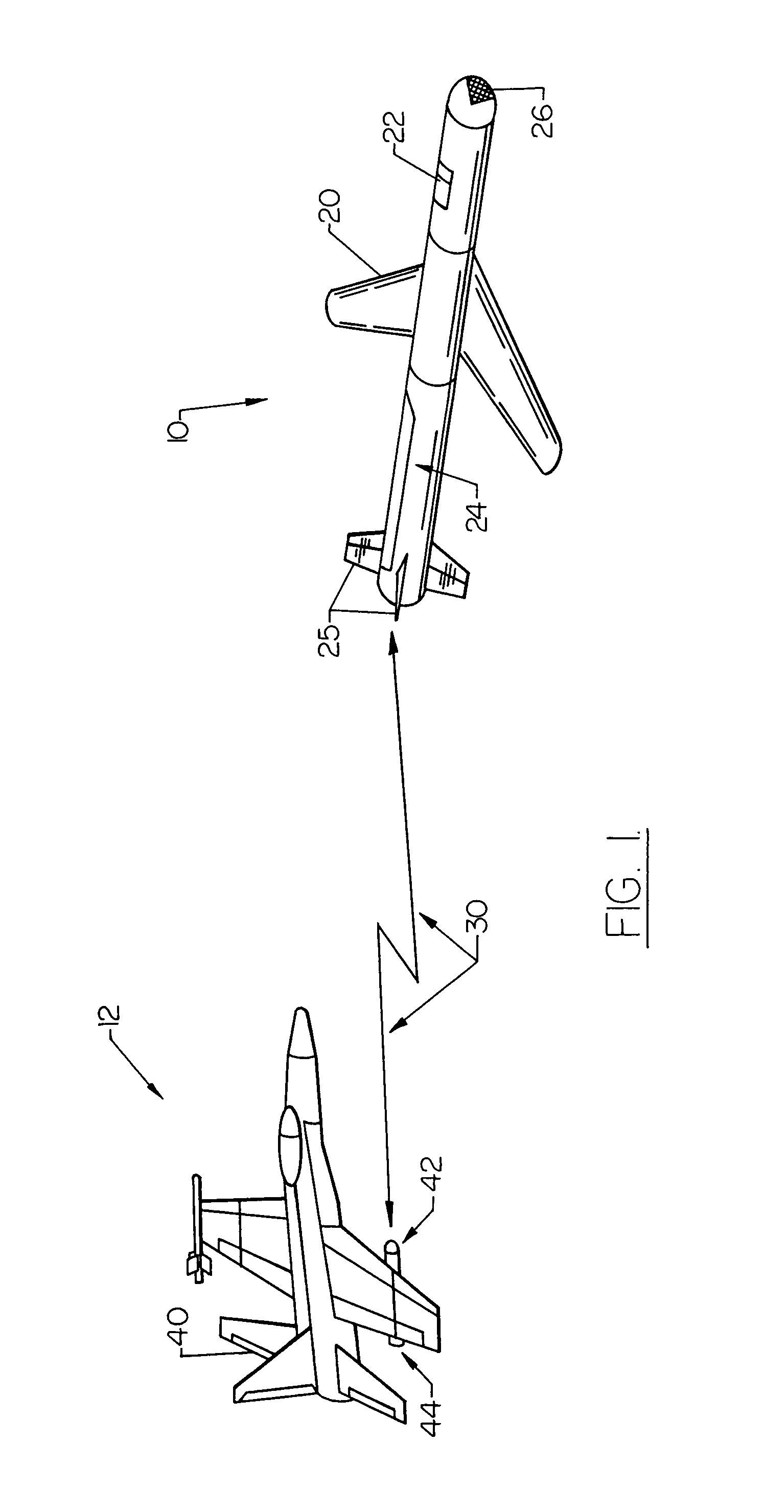
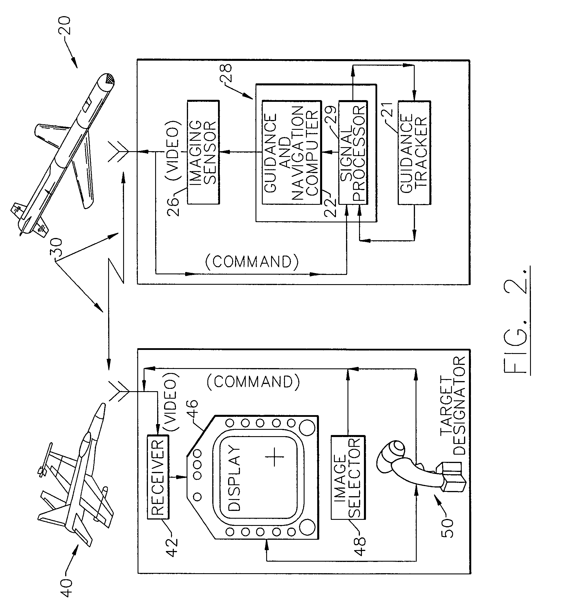
[0034]Referring more particularly to the drawings, FIGS. 1-3 illustrate one embodiment of the invention in which the remote aerial vehicle 10 is an airborne missile 20 and the control center 12 is an aircraft 40. For example, the aircraft may be a McDonnell Douglas F / A-18 airplane, and the missile may be a McDonnell Douglas Standoff Land Attack Missile Expanded Response (SLAM ER). The missile 20 is typically launched from the aircraft 40 and flown to a predetermined target area (not shown). Once the missile 20 is launched, a guidance and navigation computer 22 located inside the body 24 of missile 20 guides the missile along a pre-programmed trajectory. Guidance of the missile 20 is accomplished by adjusting the control surfaces 25 in response to commands issued by the guidance and navigation computer 22.

[0035]The missile 20 comprises imaging means 26, preferably located in the nose portion of the missile. Imaging means 26, however, may be located anywhere on the missile which provi...


PUM


Abstract

A system and method of guiding a remote aerial vehicle toward a designated target includes an imaging sensor which generates sequential video images of the target area from the remote aerial vehicle and transmits the images to a control center via the video portion of a communications data link. The control center receives and displays the plurality of video images on a video display. An image selection signal is generated at the control center and transmitted to the remote aerial vehicle for commanding the imaging sensor to continuously transmit one of the sequential video images. A target designation signal, corresponding to the azimuth and elevation of the desired target on the continuously displayed video image, is generated and transmitted via a command portion of the data link to the remote aerial vehicle. The target designation signal is processed and an updated target position is computed to compensate for time delays. A tracker tracks the updated target position to thereby guide the remote aerial vehicle toward the designated target. The video images and the target designation signal may be transmitted at low bandwidth frequencies to a satellite and relayed to the control center and the remote aerial vehicle respectively.

Description

FIELD OF THE INVENTION[0001]The present invention relates to real-time target designation for a remote aerial vehicle, and more particularly to man-in-the-loop (MITL) control of an airborne missile.BACKGROUND OF THE INVENTION[0002]MITL control of remote aerial vehicles provides a level of accuracy and real-time adaptability which fully autonomous systems generally cannot provide. Thus, MITL control is commonly used to designate a desired target for an airborne missile. MITL control of an airborne missile is typically accomplished by a terminal sensor mounted in the nose of the missile which transmits sequential video images of the target area, via the video portion of a communications data link, to a control center.[0003]The control center is equipped to receive and display the sequential video images to an operator. The operator designates the target, or aimpoint, from the video images on the display. The position of the target on the display is then transmitted, in the form of a t...

Claims


Application Information

Patent Timeline
IPC IPC(8): F41G7/22G05D1/00
CPCF41G7/2206G05D1/0033B64C2201/146B64C2201/121F41G7/2253F41G7/2293B64U2101/19B64U2101/15B64U2201/20
Inventor HYSLOP, GREGORY L.KRAEMER, JOHN W.MIZGATE, KURT A.
Owner THE BOEING CO
Learn More