
Dual frequency control of buck-boost regulator with a pass through band

a buck-boost regulator and pass through technology, applied in the direction of electric variable regulation, process and machine control, instruments, etc., can solve the problems of high power loss, achieve low power loss, high power loss, and satisfy current balan

Active Publication Date: 2015-09-01
HUAWEI DIGITAL POWER TECH CO LTD
View PDF7 Cites 5 Cited by
  • Summary
  • Abstract
  • Description
  • Claims
  • Application Information

AI Technical Summary

Benefits of technology

The patent describes a new approach to maintaining balance between positive and negative input leads of multiple non-isolated voltage regulators that reduces power loss. This is achieved through a buck-boost regulator that uses dual-frequency control of first and second switching circuitry. This allows for efficient power transfer with low power loss and effective current control. The technical effect is reduced power loss and improved efficiency in voltage regulation.

Problems solved by technology

Conventional approaches to maintaining satisfactory current balance between positive and negative input leads of a plurality of parallel non-isolated voltage regulators can result in high power loss.

Method used


Image

  • Dual frequency control of buck-boost regulator with a pass through band
  • Dual frequency control of buck-boost regulator with a pass through band
  • Dual frequency control of buck-boost regulator with a pass through band

Examples


Embodiment Construction

[0028]Reference will now be made in detail to various embodiments, examples of which are illustrated in the accompanying drawings. While descriptions will be provided in conjunction with these embodiments, it will be understood that the descriptions are not intended to limit the scope of the embodiments. On the contrary, the disclosure is intended to cover alternatives, modifications and equivalents, of these embodiments. Furthermore, in the following description, numerous specific details are set forth in order to provide a thorough understanding of embodiments. In other instances, well-known methods, procedures, components, and circuits have not been described in detail as not to unnecessarily obscure aspects of embodiments.

Exemplary Operational Setting of Buck-Boost Regulator Having Dual Frequency Control with a Pass Through Band According to One Embodiment

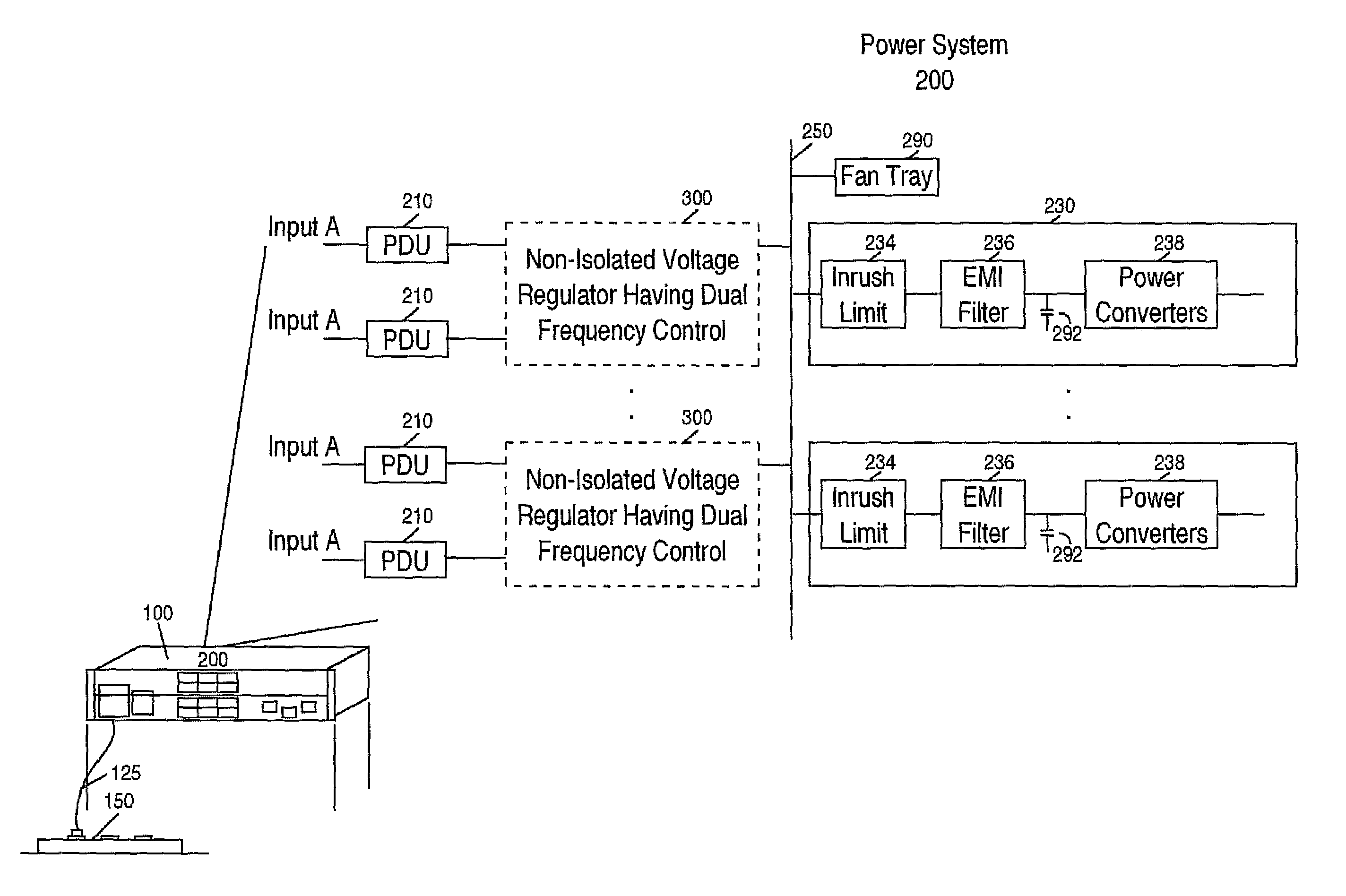
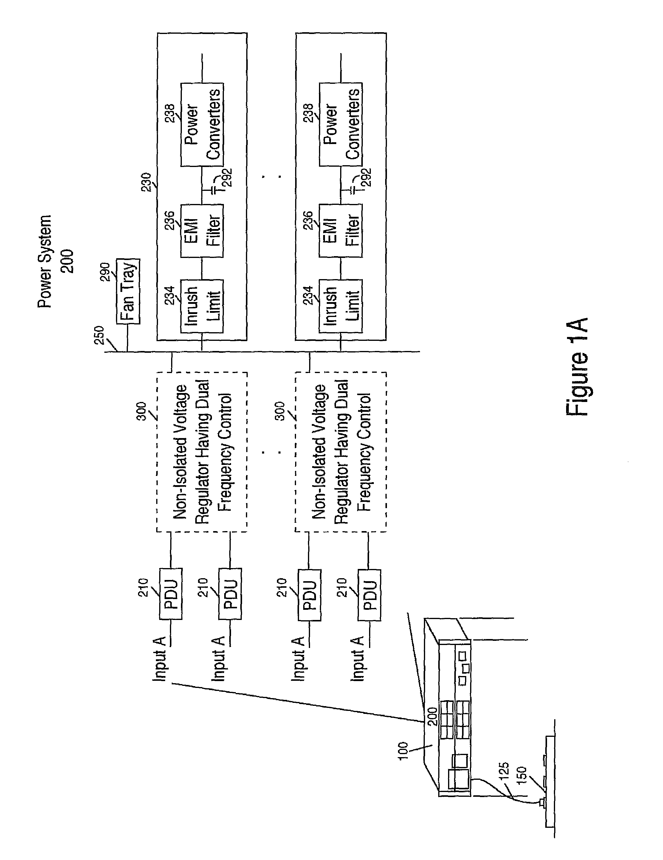
[0029]FIG. 1A shows an exemplary operational setting of a buck-boost voltage regulator 300 (e.g., non-isolated) having dual f...


PUM


Abstract

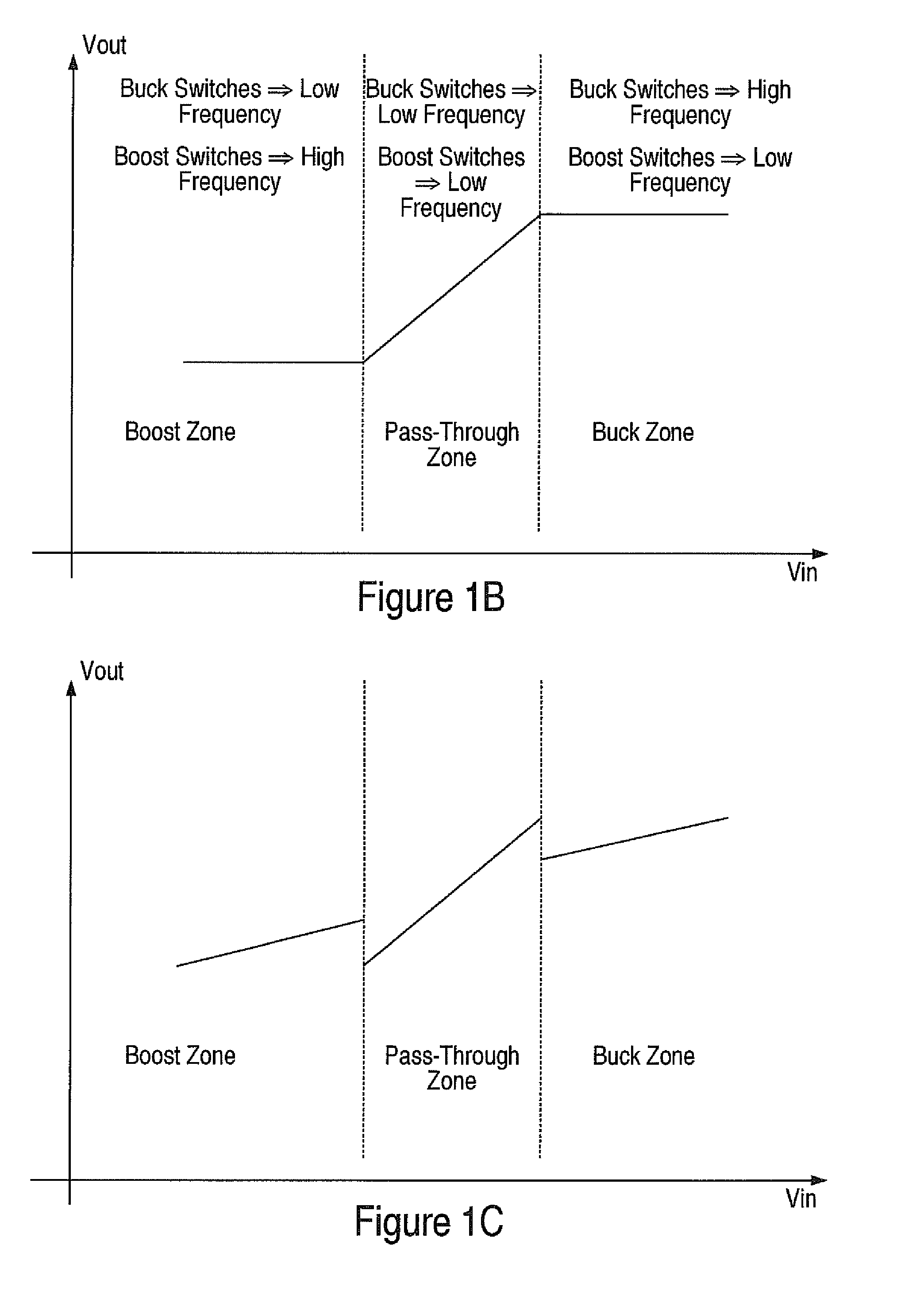
Dual frequency control of first and second pairs of switches of a buck-boost regulator with pass through band is disclosed. In buck and boost modes respectively a first pair of the switches is operated at high frequency and a second pair of the switches is operated at low frequency. In pass through mode, both pairs of switches are operated at low frequency. Dual frequency control and operation of the pairs of switches enables current sharing between positive and negative power leads in buck, boost and pass-through modes.

Description

BACKGROUND[0001]Electronic equipment includes groupings of electronic circuits and components that are designed to provide one or more complex functions. The electronic equipment receives power from an energy source that is used to power its electronic circuits and components. The power that is received is input to a power system of the electronic equipment that provides voltage outputs that are delivered to a plurality of loads. The power system often includes one or more voltage regulators that operate in parallel.[0002]Voltage regulators are used to regulate the power that is delivered to one or more circuit cards such that voltage and current stresses on components that reside on a circuit card are reduced. They are used to convert an input voltage that is received from a given energy source to an output voltage that falls within a voltage range that is suitable for the components that reside on the circuit cards. By using a voltage regulator in the power system of electronics e...

Claims


Application Information

Patent Timeline
Patent Type & Authority Patents(United States)
IPC IPC(8): G05F1/24G06F1/00G05F3/02G06F1/26
CPCG05F3/02G06F1/26
Inventor MAO, HENGCHUNLIU, YAN-FEI
Owner HUAWEI DIGITAL POWER TECH CO LTD
Learn More