Tyre with specified belt structure
Active Publication Date: 2016-05-24
PIRELLI TYRE SPA
View PDF34 Cites 1 Cited by
Summary
Abstract
Description
Claims
Application Information
AI Technical Summary
This helps you quickly interpret patents by identifying the three key elements:
Problems solved by technology
Method used
Benefits of technology
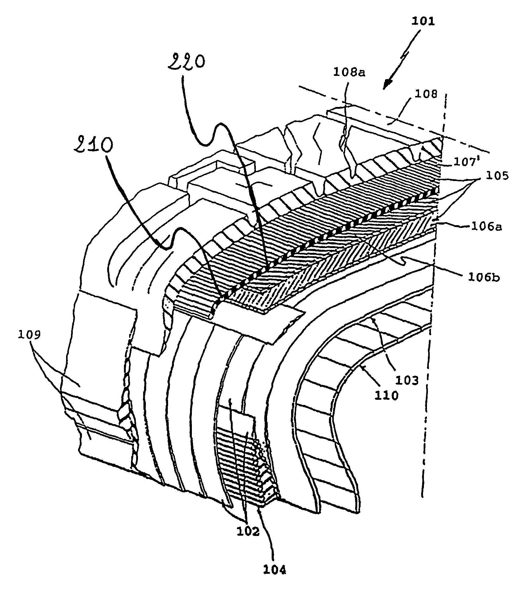
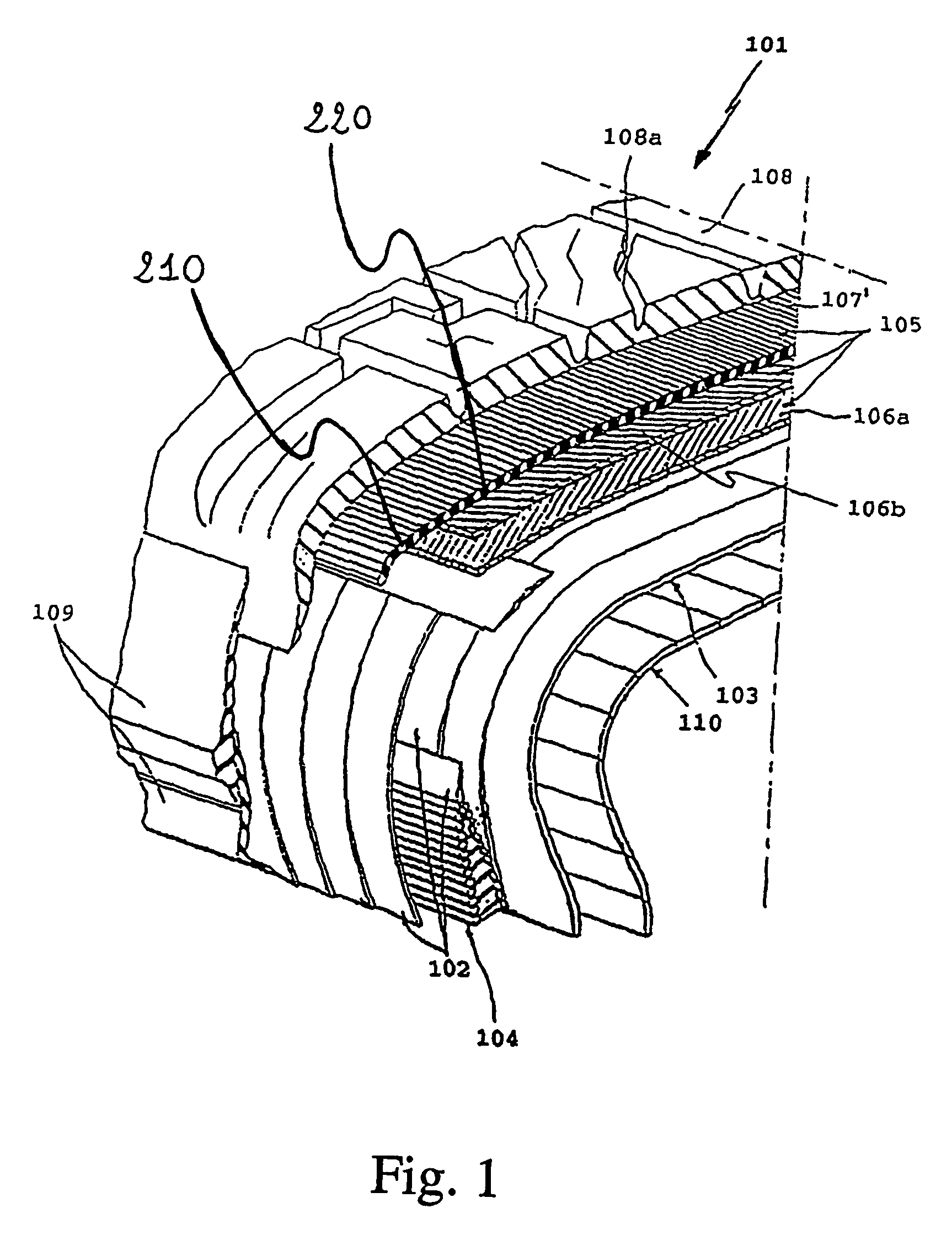
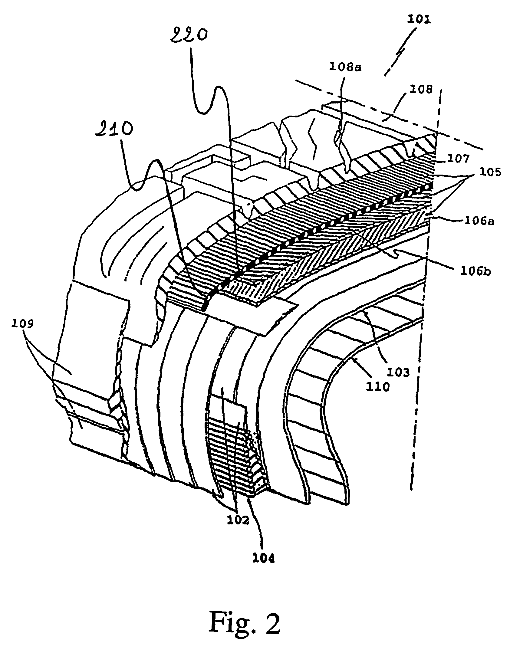
The invention provides a pneumatic tyre with a belt structure that can limit lifting without affecting the performance of the tyre. The belt layer guarantees a good balance of lifting and overall performance of the tyre during high-speed running. The rigidity of the belt layer can be modified by varying the ratio of the density of two elongated elements. Increasing the density of the first elongated element in the tyre shoulders improves the behavior with respect to aquaplaning, while maintaining a constant ratio of the two elongated elements over the axial width of the belt layer ensures a uniform and homogeneous distribution of the turns.
Problems solved by technology
The Applicant has noticed that, if the tyre is provided with a stiff belt layer in a position radially external to the conventional crossed belt plies, said belt layer succeeds in preventing the lifting phenomenon, but negatively impacts on the tyre performances as well as on the tyre manufacturing process.
In particular, in case the tyre is provided with a very stiff belt layer, said belt layer negatively influences the tyre performances such as: a) the handling, in the sense that even if the car becomes more reactive to the commands given by the driver through the steering wheel, the increased rigidity affects the car suspension system causing a perceivable and tedious roll of the car compartment; b) the ride comfort, especially in the case a bump present on the road has to be overcome (the so-called “plastic comfort”); c) the “acoustic comfort”, which represents the level of the noise perceived by the driver inside the passenger compartment due to the tyre structure.
Method used
Image
Click on the blue label to locate the original text in one second.
Reading with bidirectional positioning of images and text.
Examples
example 1
[0092]Five distinct strip-like bands were produced by using the following cords:
[0093]cord A: AR / NY 1670 / 1400 (260 / 70)×260
[0094]cord B: NY 1400 / 2 270×270
[0095]cord C NY 1400 / 1 150Z
[0096]wherein cord A—which is the first elongated element according to the present invention—is a hybrid cord consisting of one aramidic fiber filament (AR) and one filament of Nylon (NY); 1670 is the count (in dTex) of the aramidic fiber filament and 1400 is the count (in dTex) of the filament of Nylon; 260 (in tpm) indicates the twist of the aramidic fiber filament, while 70 (in tpm) indicates the twist of the Nylon filament; ×260 (in tpm) indicates the cord twist.;
[0097]wherein cord B—which is the second elongated element according to the present invention—is a cord consisting of two filaments of Nylon; 1400 is the count (in dTex) of the two filaments of Nylon; 270 (in tpm) indicates the twist of each filament of Nylon; ×270 (in tpm) indicates the cord twist, and
[0098]wherein cord C—which is the second ...
example 2
[0109]Five tyres 1 to 5, having size 235 / 35 R19, were manufactured by using respectively the strip-like bands 1) to 5) of Example 1.
[0110]The tyres 1 to 5 had identical structural elements (e.g. identical carcass, crossed belt plies, bead cores, tread band) but for the 0° belt layer positioned radially external to the crossed belt plies, said 0° belt layer having been produced by using the different strip-like bands of Example 1.
[0111]Furthermore, the 0° belt layers of the tyres 2 to 5 consisted of two layers obtained by spirally winding twice the strip-like bands 2) to 5) respectively, while the 0° belt layer of the tyre 1 consisted of only one layer obtained by spirally winding twice the strip-like band 1).
[0112]Indoor and outdoor testings were carried out on the tyres 1 to 5.
[0113]Indoor Testings
[0114]a) Tyre diameter variation[0115]The tyre was rotated against a road wheel at increasing speeds. In more details, the road wheel was rotated from 20 km / h to 260 km / h; the speed was i...
PUM
Property
Measurement
Unit
Fraction
aaaaa
aaaaa
Fraction
aaaaa
aaaaa
Time
aaaaa
aaaaa
Abstract
A tire includes a carcass, a belt structure, and a tread band. The belt structure includes at least two belt plies and at least one belt layer radially external to the belt plies. The at least one belt layer extends at least for an axial width of the at least two belt plies and includes at least one first elongated element and at least one second elongated element. The elongated elements form turns substantially oriented in a circumferential direction of the tire. The turns are alternately disposed along an axial development of the at least one belt layer. The at least one first elongated element is a hybrid cord including at least one high-elastic-modulus filament and at least one low-elastic-modulus filament that are twisted together. An elastic modulus of the at least one second elongated element is lower than an elastic modulus of the at least one first elongated element.
Description
CROSS-REFERENCE TO RELATED APPLICATIONS[0001]This application is a national-phase entry under 35 U.S.C. §371 from International Application No. PCT / EP2003 / 006495, filed Jun. 19, 2003, in the European Patent Office, the content of which is relied upon and incorporated herein by reference.BACKGROUND OF THE INVENTION[0002]1. Field of the Invention[0003]The present invention relates to a tyre for motor vehicles.[0004]In particular, the present invention relates to high performance tyres such as, for example, tyres designed for high-powered cars or, more generally, tyres intended for applications involving high operating speeds.[0005]In more details, the present invention relates to “HP” (High Performance) or “UHP” (Ultra High Performance) tyres.[0006]2. Description of the Related Art[0007]High speed running, e g. higher than 200 km / h, generates remarkable centrifugal forces at the tread of the tyre due to the rotation thereof.[0008]Said centrifugal forces cause the tyre tread to swell o...
Claims
Application Information
Patent Timeline
Application Date:The date an application was filed.
Publication Date:The date a patent or application was officially published.
First Publication Date:The earliest publication date of a patent with the same application number.
Issue Date:Publication date of the patent grant document.
PCT Entry Date:The Entry date of PCT National Phase.
Estimated Expiry Date:The statutory expiry date of a patent right according to the Patent Law, and it is the longest term of protection that the patent right can achieve without the termination of the patent right due to other reasons(Term extension factor has been taken into account ).
Invalid Date:Actual expiry date is based on effective date or publication date of legal transaction data of invalid patent.