Impedance matching apparatus

a technology of impedance matching and apparatus, which is applied in the direction of electrical apparatus, transmission, multiple-port network, etc., can solve the problems of affecting the efficiency of impedance matching, and affecting the performance of wireless networks, so as to prevent the impedance matching efficiency and facilitate switching , the effect of minimizing the parasitic component generated by the switch

Active Publication Date: 2015-09-01
LG INNOTEK CO LTD
View PDF12 Cites 4 Cited by
  • Summary
  • Abstract
  • Description
  • Claims
  • Application Information

AI Technical Summary

Benefits of technology

[0013]As described above, according to the disclosure, the impedance matching is not performed at a specific frequency range, thereby preventing the impedance matching efficiency from being degraded due to the insertion loss of the matching module.
[0014]In addition, according to the disclosure, the RF signal is easily switched to the bypass path by using a switch.
[0015]In addition, according to the disclosure, the RF MEMS switch is used, so that the parasitic component generated from a switch can be minimized.
[0016]Further, according to the disclosure, the double pole-type switch is provided in the RF front end as the switch instead of the single pole-type switch, thereby facilitating switch installation.

Problems solved by technology

Although a conventional variable impedance matching apparatus can easily adjust a frequency to obtain a desirable antenna resonance point, the insertion loss of predetermined dB may be caused due to the characteristic of the variable impedance matching apparatus including active variable devices.
Accordingly, the insertion loss of the variable impedance matching apparatus becomes greater than the insertion loss of a fixed impedance matching apparatus at a specific frequency range, so that the wireless performance may be deteriorated.

Method used


Image

  • Impedance matching apparatus
  • Impedance matching apparatus
  • Impedance matching apparatus

Examples


Embodiment Construction

[0021]Hereinafter, embodiments of the disclosure will be described in detail with reference to drawings.

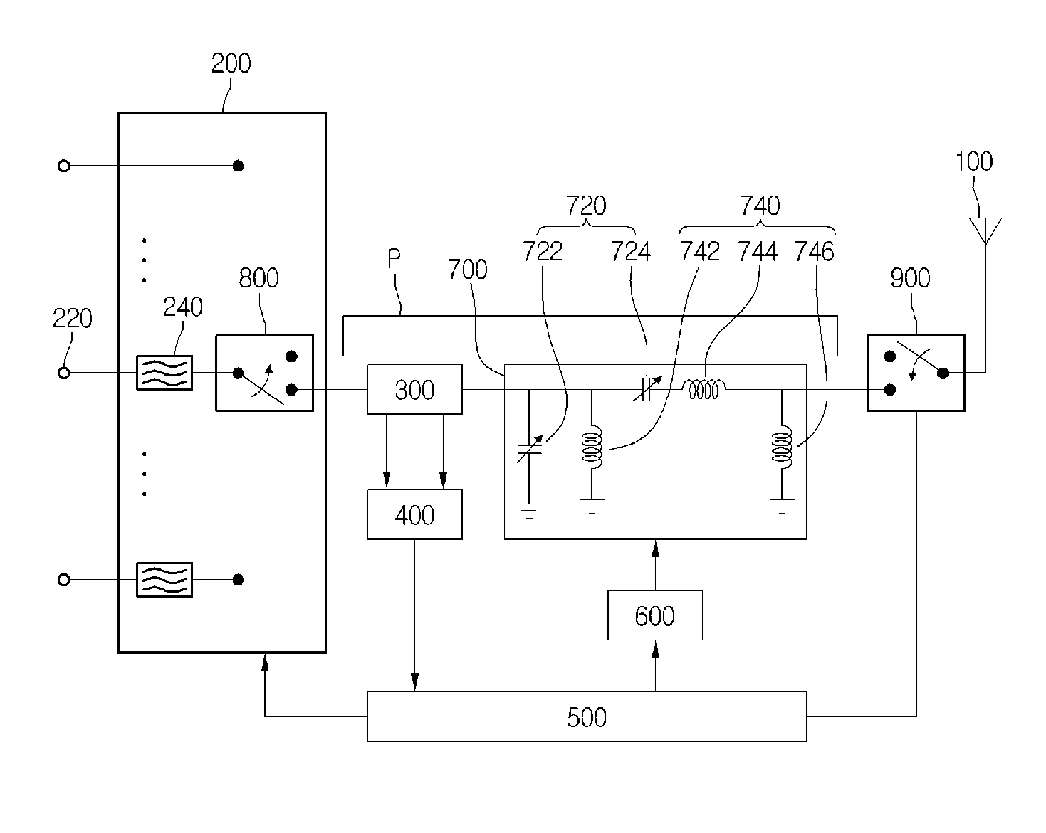
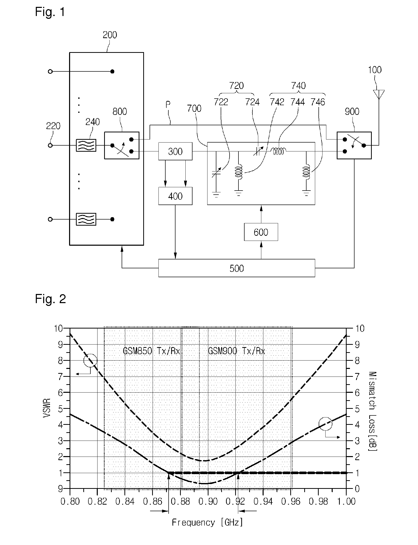
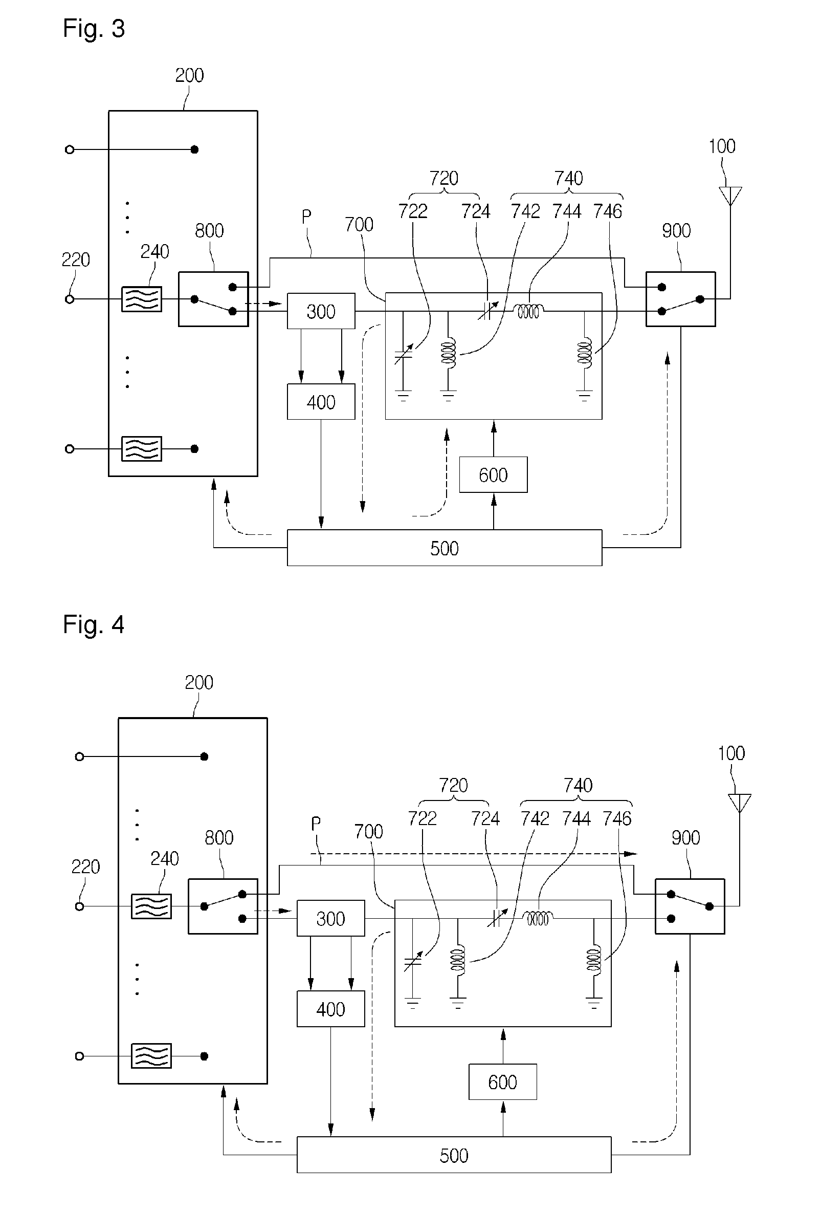
[0022]FIG. 1 is a block diagram showing an impedance matching apparatus including a switch module according to the disclosure, FIG. 2 is a graph showing mismatch loss according to insertion loss of the impedance matching apparatus according to the disclosure, and FIGS. 3 and 4 are block diagrams showing the operation of the switch module according to the disclosure.

[0023]Referring to FIG. 1, the impedance matching apparatus according to the disclosure includes an RF front end 200 to provide a multi-band RF signal, a reflected power measuring module 300 to measure the reflection coefficient for the RF input signal, a matching module 700 to adjust a variable capacitor 720 so that the reflection coefficient is minimized, switching modules 800 and 900 to selectively switch the RF signal onto a bypass path P, and a controller 500 to apply a control signal so that the RF signal is switc...


PUM


Abstract

Disclosed is an impedance matching apparatus performing impedance matching between a front-end module and an antenna. The impedance matching apparatus includes an RF front end providing a multi-band RF signal, a reflected power measuring module measuring a reflection coefficient for the RF input signal, a matching unit adjusting impedance so that the reflection coefficient is minimized, a first switch module provided in the RF front end to selectively switch the RF signal onto a bypass path, and a controller allowing the RF signal to be switched onto the bypass path if a specific frequency range is detected from the reflection coefficient.

Description

CROSS-REFERENCE TO RELATED APPLICATIONS[0001]This application is the U.S. national stage application of International Patent Application No. PCT / KR2012 / 006202, filed Aug. 3, 2012, which claims priority to Korean Application No. 10-2011-0078626, filed Aug. 8, 2011, the disclosures of each of which are incorporated herein by reference in their entirety.TECHNICAL FIELD[0002]The disclosure relates to an impedance matching apparatus. In more particular, the disclosure relates to an impedance matching apparatus capable of improving wireless performance.BACKGROUND ART[0003]In general, a mobile communication terminal has been broadbanded to employ a global system for mobile communication (GSM) scheme / a wideband code division multiple access (WCDMA) scheme which are different communication schemes.[0004]To this end, an antenna apparatus of the mobile communication terminal includes an antenna, and a front-end module connected with the antenna, and further includes a variable impedance matchi...

Claims


Application Information

Patent Timeline
Patent Type & Authority Patents(United States)
IPC IPC(8): H03H7/38H04B1/18H04B1/04H03H7/40
CPCH03H7/38H03H7/40H04B1/0458H04B1/18
Inventor LEE, SANG HUN
Owner LG INNOTEK CO LTD
Why Eureka
Try Eureka