
Method and apparatus of controlling quality of printed image for color printing press

a color printing press and printing quality technology, applied in office printing, color measuring devices, printing, etc., can solve the problems of large degree, adverse changes in color that has been matched prior to printing, adverse changes in color, etc., and achieve accurate matching

Inactive Publication Date: 2012-03-06
RYOBI
View PDF11 Cites 0 Cited by
  • Summary
  • Abstract
  • Description
  • Claims
  • Application Information

AI Technical Summary

Benefits of technology

This approach allows for precise matching of tints and hues in printed images, reducing variations in solid ink density and achieving high accuracy in color matching, even when tints or hues change during printing.

Problems solved by technology

While each ink generally includes a color component of the other ink as turbidity, the turbidity degree adversely changes to a large degree if two inks become mixed by the other ink moving to the ink fountain via the group of ink rollers during printing operation is made in the manner as described above, or the color that has been matched prior to printing adversely changes during the printing if a transfer ratio of one ink to be printed onto another ink (ink trapping ratio) changes.
Therefore, there is a case in which the tints or hues of the colors do not match, leaving much to be improved.

Method used


Image

  • Method and apparatus of controlling quality of printed image for color printing press
  • Method and apparatus of controlling quality of printed image for color printing press
  • Method and apparatus of controlling quality of printed image for color printing press

Examples


Embodiment Construction

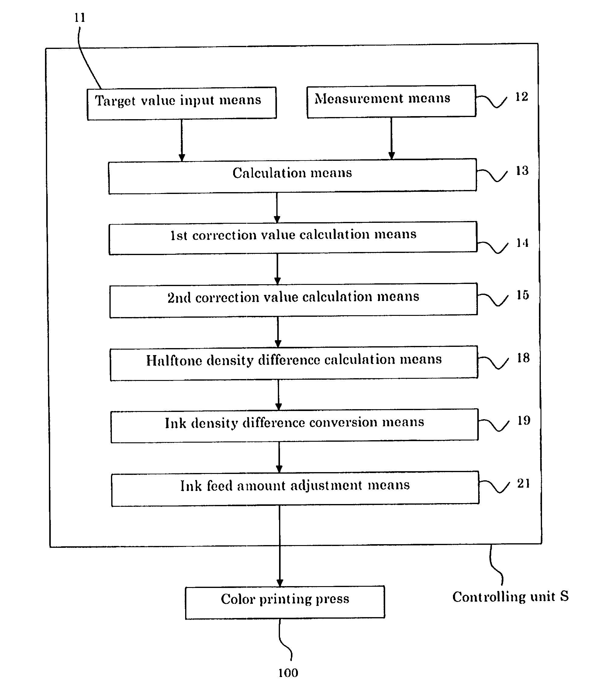
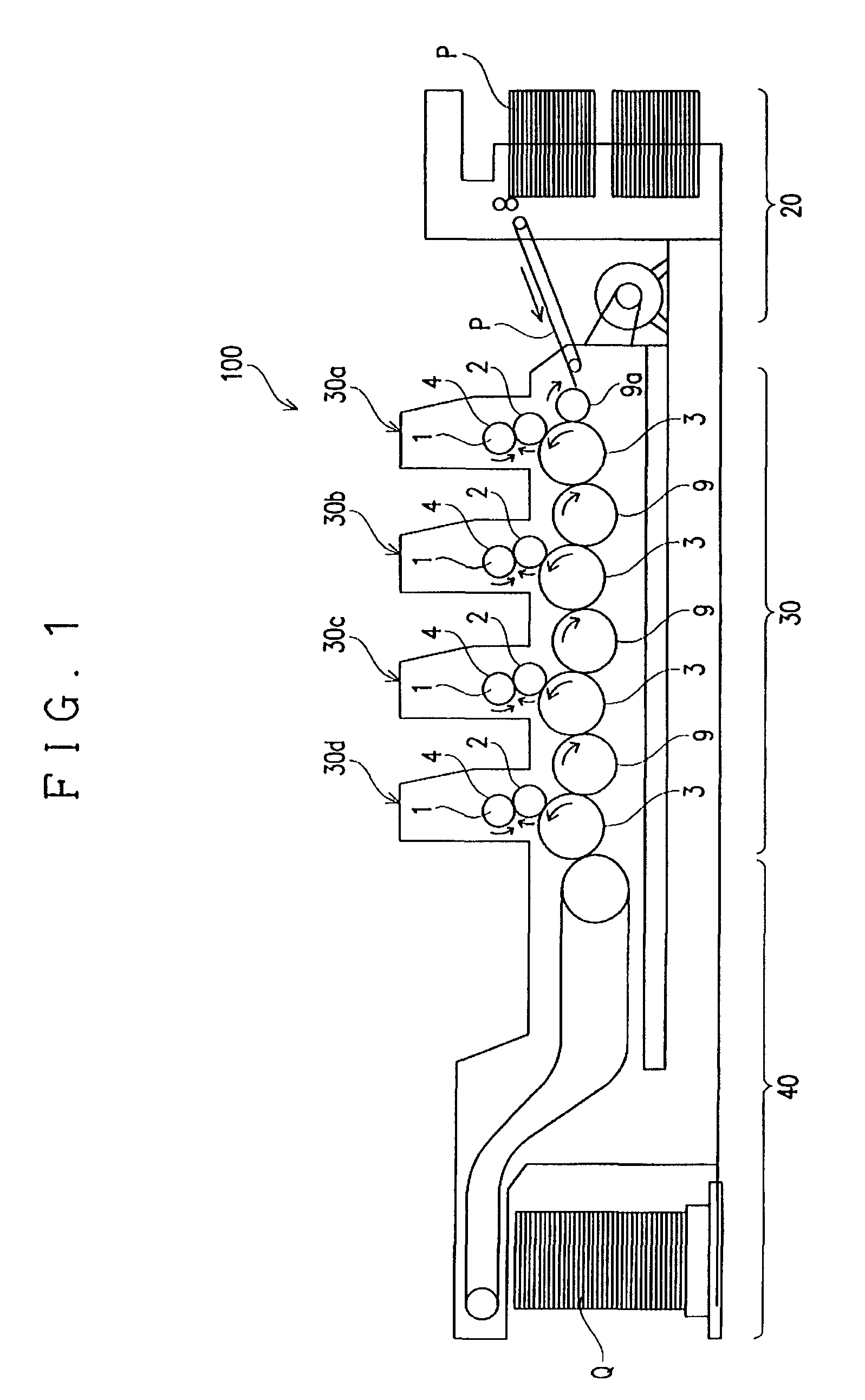
[0026]The following describes an embodiment according to the present invention with reference to the drawings. FIG. 1 shows a schematic configuration of one example of a color printing press 100 in one example of a color printing system that realizes a method of controlling quality of a printed image for a color printing press according to the present invention. The color printing system is provided with a controlling unit S as shown in FIG. 3 that will be described later, in addition to the color printing press 100 as described above.

[0027]As shown in FIG. 1, the color printing press 100 prints images in basic colors of C, M, Y, and Bk that are formed by printing inks of a plurality of basic colors that are different from each other, which are the inks of four basic colors of Cyan (C), Magenta (M), Yellow (Y), and Black (Bk) in this specification, sequentially on a subject to be printed P (printing paper in this specification), thereby printing a color print image onto the subject ...


PUM


Abstract

A method and an apparatus of the present invention is capable of matching an image of a printed matter with a desired image with high accuracy by adjusting tints even when tints change while printing. There are provided a measurement means that measures gray Lab values of a printed matter, a calculation means that calculates ΔL, Δa, and Δb that are differences between the measured Lab values and predetermined target gray Lab values, a first correction value calculation means that corrects Δa based on Δb, a second correction value calculation means that corrects ΔL based on a corrected value Δa1 that has been calculated by the first correction value calculation means, a halftone density difference calculation means that calculates halftone density differences of C, M, and Y based on Δb, Δa1 and ΔL1 obtained by correcting ΔL, an ink density difference conversion means that converts the calculated C, M, and Y halftone density differences into ink density differences, and an ink feed amount adjustment means that adjusts the ink feed amount for the ink fountain keys based on the ink density differences.

Description

CROSS REFERENCE TO RELATED APPLICATION[0001]This application claims priority from Japanese Patent Application No. 2008-018529, which is incorporated herein by reference.BACKGROUND OF THE INVENTION[0002]1. Field of the Invention[0003]The present invention relates to a method of controlling quality of a printed image and an apparatus of controlling quality of a printed image by controlling the ink feed amount of each of a plurality of basic colors of a color printing press.[0004]2. Related Art[0005]There has been known a color printing press including a plurality of printing units each provided with a plurality of ink fountains that respectively contain printing inks of a plurality of basic colors that are different from each other (typically four colors including three colors of Cyan (C), Magenta (M), and Yellow (Y), as well as Black (Bk)), and a plurality of ink fountain keys each aligned with each of the ink fountains in the lengthwise direction so as to adjust ink feed amounts fro...

Claims


Application Information

Patent Timeline
Patent Type & Authority Patents(United States)
IPC IPC(8): B41F31/02G01J3/46B41F33/14
CPCB41F31/02B41F31/13B41F33/0045
Inventor SUGIMOTO, HIROSHI
Owner RYOBI
Learn More