Outer conductor mounting structure for connector, and connector

A technology of installation structure and outer conductor, which is applied in the direction of connection, parts of electrical measuring instruments, instruments, etc., can solve the problems of affecting test results, inconvenient operation, and inconsistency in layout

Pending Publication Date: 2021-04-13
COMBA RF TECH GUANGZHOU LTD +1
View PDF0 Cites 0 Cited by
  • Summary
  • Abstract
  • Description
  • Claims
  • Application Information

AI Technical Summary

Problems solved by technology

[0003] However, there are space limitations in the design of microstrip lines on printed boards, especially in the state of multi-channel (up to 64 channels), the layout of the lead-out direction of microstrip lines cannot be consistent, resulting in very compact vertical or The layout of the microstrip line lead-out direction, such as mirroring, puts forward higher requirements for the connectors used for testing.
When traditional connectors are used to test the microstrip line on the PCB, it often occurs that the installed connectors interfere with each other or require a variety of connectors with different notch directions to cooperate with the test on the same multi-channel PCB board, which is not only inconvenient to operate , and it is also easy to affect the test results

Method used


Image

  • Outer conductor mounting structure for connector, and connector
  • Outer conductor mounting structure for connector, and connector
  • Outer conductor mounting structure for connector, and connector

Examples


Embodiment Construction

[0040] Embodiments of the present invention are described in detail below in conjunction with accompanying drawings:

[0041] In order to make the above objects, features and advantages of the present invention more comprehensible, specific implementations of the present invention will be described in detail below in conjunction with the accompanying drawings. In the following description, numerous specific details are set forth in order to provide a thorough understanding of the present invention. However, the present invention can be implemented in many other ways different from those described here, and those skilled in the art can make similar improvements without departing from the connotation of the present invention, so the present invention is not limited by the specific embodiments disclosed below.

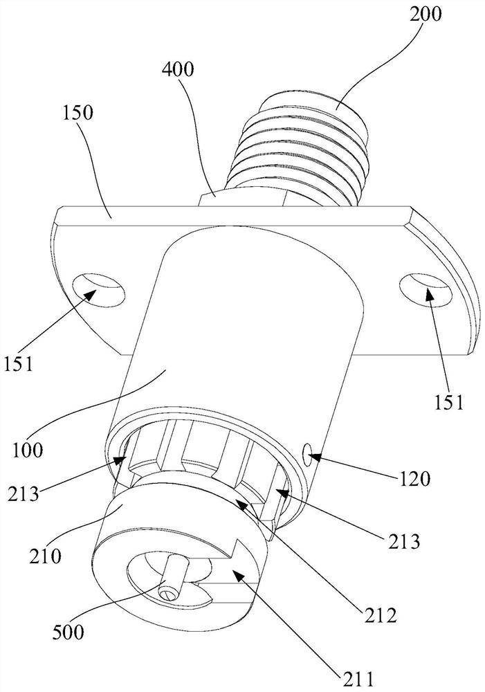
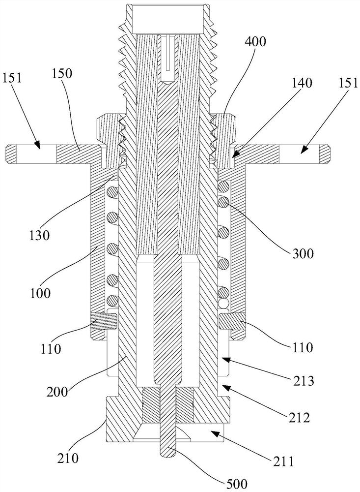
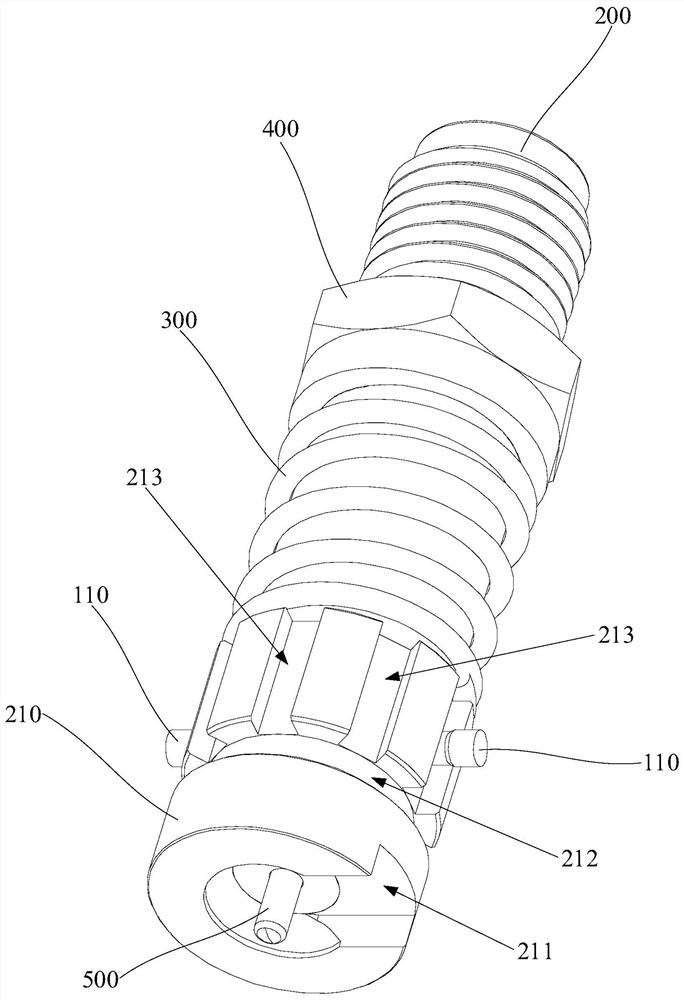
[0042] Please refer to Figure 1 to Figure 3 , an embodiment provides a mounting structure for an outer conductor 200 for a connector, including a flange ring 100 and an...


PUM


Abstract

The invention discloses an outer conductor mounting structure for a connector, and the connector. The outer conductor mounting structure for the connector comprises a flange ring and an outer conductor, wherein the flange ring is provided with a limiting piece, the outer conductor is sleeved with the flange ring, the outer conductor is provided with an avoiding notch, an annular groove and a strip-shaped groove, the annular groove is formed around the periphery of the outer conductor, the strip-shaped groove extends in the length direction of the outer conductor, one end of the strip-shaped groove extends into the annular groove, and the strip-shaped groove and the annular groove are both arranged corresponding to the limiting piece. The connector comprises an inner conductor and an outer conductor mounting structure for the connector, wherein the inner conductor is arranged in the mounting through cavity of the outer conductor. According to the invention, the limiting piece can slide along the strip-shaped groove so as to make the outer conductor move in the length direction of the flange ring, and after the limiting piece slides to the annular groove through the strip-shaped groove, the outer conductor rotates automatically through cooperation of the limiting piece and the annular groove, so that the limiting piece can reach the other strip-shaped groove so as to achieve position adjustment of the receding notch, and the avoidance gap is matched with the position of the microstrip line.

Description

technical field [0001] The invention relates to the technical field of electronic device detection, in particular to an outer conductor installation structure for a connector and the connector. Background technique [0002] The connector used to test the RF signal of the microstrip line on the PCB printed board usually has an avoidance gap at the ground end of the outer conductor of the connector to avoid the microstrip line. During the test, the notch position of the outer conductor should be directly above the microstrip line on the printed board. [0003] However, there are space limitations in the design of microstrip lines on printed boards, especially in the state of multi-channel (up to 64 channels), the layout of the lead-out direction of microstrip lines cannot be consistent, resulting in very compact vertical or The layout of the microstrip line lead-out direction, such as mirroring, puts forward higher requirements for the connectors used for testing. When tradi...

Claims


Application Information

Patent Timeline
Patent Type & Authority Applications(China)
IPC IPC(8): H01R12/70G01R1/04
CPCG01R1/0416H01R12/7011
Inventor 党志南
Owner COMBA RF TECH GUANGZHOU LTD
Why Eureka
Try Eureka