Papillary muscle position control devices, systems, and methods

a technology of position control device and papillary muscle, applied in the field of heart valve repair device and method, can solve the problems of reducing life quality, significant disability, and killing approximately 950,000 people, and achieve the effect of reducing and eliminating blood flow regurgitation

a technology of position control device and papillary muscle, applied in the field of heart valve repair device and method, can solve the problems of reducing life quality, significant disability, and killing approximately 950,000 people, and achieve the effect of reducing and eliminating blood flow regurgitation

US9125742B2Active Publication Date: 2015-09-08GEORGIA TECH RES CORP

Image

  • Papillary muscle position control devices, systems, and methods
  • Papillary muscle position control devices, systems, and methods
  • Papillary muscle position control devices, systems, and methods

Examples


Embodiment Construction

[0041]Referring now to the figures, wherein like reference numerals represent like parts throughout the several views, exemplary embodiments of the present invention will be described in detail. Throughout this description, various components may be identified having specific values or parameters, however, these items are provided as exemplary embodiments. For example, it should be understood that while some embodiments are discussed with specific reference to mitral valves, embodiments of the present invention can be utilized in conjunction with any atrioventricular valve. Thus, the exemplary embodiments do not limit the various aspects and concepts of the present invention as many comparable parameters, sizes, ranges, and / or values may be implemented.

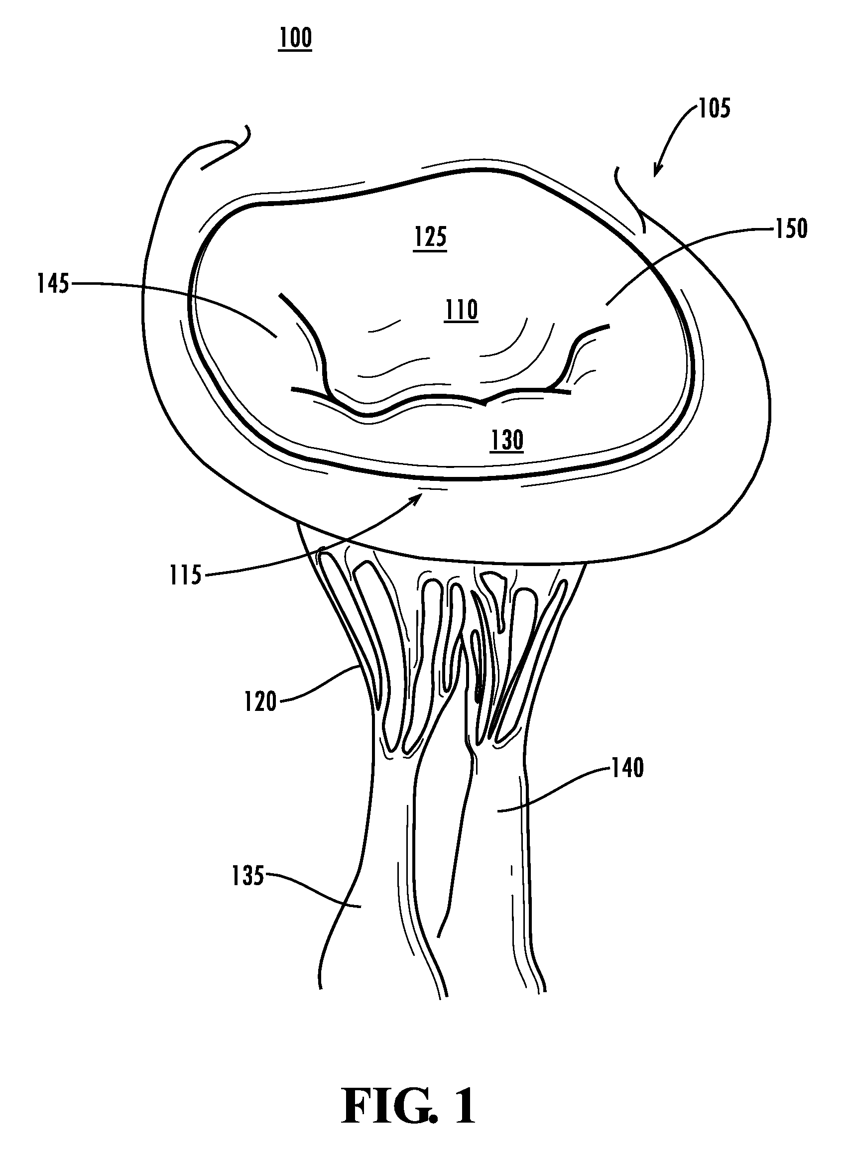
[0042]FIG. 1 illustrates a mitral valve 100. As shown, the mitral valve 100 includes a mitral annulus 105, an anterior mitral leaflet 110, a posterior mitral leaflet 115, chordae tendineae 120, and medial and lateral papillary muscles...


PUM


Abstract

Papillary muscle position control devices (900) systems and methods are provided. According to an exemplary embodiment, a papillary muscle position control device generally comprises a first anchor (905), a second anchor (920), and a support structure (915). The first anchor can be configured to fixedly connect to an in situ valve of a heart ventricle. The second anchor can be configured to fixedly connect to a muscle wall of the valve. The support structure can be configured to have an adjustable length and be coupled to the first anchor and second anchor such that adjusting the length of the support structure varies a distance between the first anchor and the second anchor. Other embodiments are also claimed and described.

Description

BENEFIT & PRIORITY CLAIMS[0001]This application is a 35 U.S.C. §371 US National Stage of International Application No. PCT / US2006 / 062185 filed 15 Dec. 2006, which claims the benefit of U.S. Ser. No. 60 / 750,561, filed 15 Dec. 2005.TECHNICAL FIELD[0002]The various embodiments of the present invention relate generally to heart valve repair devices and methods, and more particularly, to devices and methods capable of positioning and controlling papillary muscles of an atrioventricular valve.BACKGROUND[0003]Cardiovascular disease accounts for nearly fifty percent of deaths in both the developed world and in developing countries. The risk of dying from heart disease is greater than the risk from AIDS and all forms of cancer combined. Cardiovascular diseases cause approximately 12 million deaths in the world each year. It is the leading cause of death in the US, killing approximately 950,000 people each year. It also accounts for a significant amount of disability and diminished quality of...

Claims


Application Information

Patent Timeline
08 Sep 2015
Publication
US9125742B2
IPC
A61F2/24
CPC
A61F2/2445; A61F2/2457; A61F2250/0004
Inventors
YOGANATHAN, AJIT P.; JIMENEZ, JORGE HERNAN