Method for a fluid-tight connection of two components for producing a fluid-tight cooling unit

a fluid-tight connection and cooling unit technology, applied in the direction of heat exchanger casings, light and heating apparatus, heat exchange apparatus, etc., can solve the problems of faulty soldering or leakage, burrs in individual sheets, burrs that are counterproductive for subsequent soldering, etc., to achieve reliable and stable connection, stable fluid-tight connection, and simple measurement

Inactive Publication Date: 2015-09-08
MAHLE BEHR GMBH & CO
View PDF16 Cites 0 Cited by
  • Summary
  • Abstract
  • Description
  • Claims
  • Application Information

AI Technical Summary

Benefits of technology

[0010]This type of embodiment of the invention is based on the realization that a component need to be solder-plated only on one side and can be cut in such a way that a remaining burr is left on the side that has not been solder-plated. This burr then no longer hinders the solder connection, so that a fluid-tight connection between the two components can be produced. The advantage of this type of an embodiment of the invention is that deburring of the first component can be omitted because of beneficial preprocessing. This avoidance of a process step has a cost-saving effect. Further, the situation can be avoided that solder in the applied solder plating is removed by deburring and as a result solder sufficient for the connection may no longer be present.
[0024]The approaches proposed above increase the likelihood of defect-free soldering or offer, among others, economic advantages in the preparation or production of individual parts and in the case of a completely soldered part. Therefore, burrs need no longer be removed during the production of the fluid-tight unit. Further, channel obstructions by excess solder can be avoided.

Problems solved by technology

During the production of the structures, the mechanical cutting processes inevitably produce burrs in the individual sheets.
These burrs are counterproductive for the subsequent soldering, because the burrs act as spacers between the sheets.
Relatively small gaps in this case can also lead to faulty soldering or to leakiness.
This is time-consuming and therefore costly.
Further, for economic reasons, sheets solder-plated in a planar manner are used, which can lead locally to a surplus of solder and thereby to undesirable narrowing or obstructions in the channels.

Method used


Image

  • Method for a fluid-tight connection of two components for producing a fluid-tight cooling unit
  • Method for a fluid-tight connection of two components for producing a fluid-tight cooling unit
  • Method for a fluid-tight connection of two components for producing a fluid-tight cooling unit

Examples


Embodiment Construction

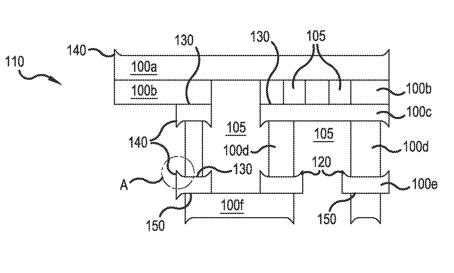
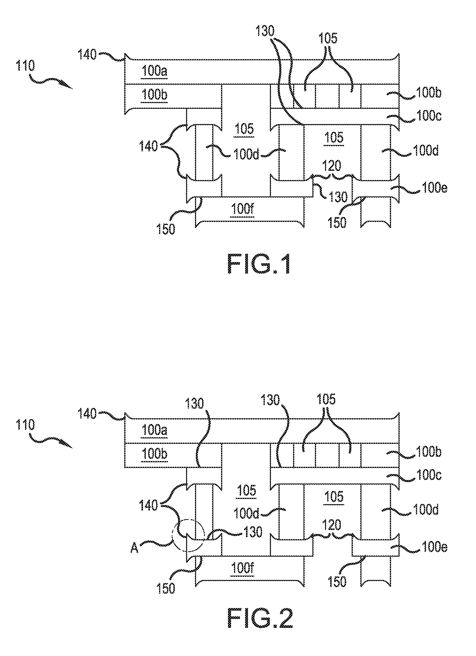
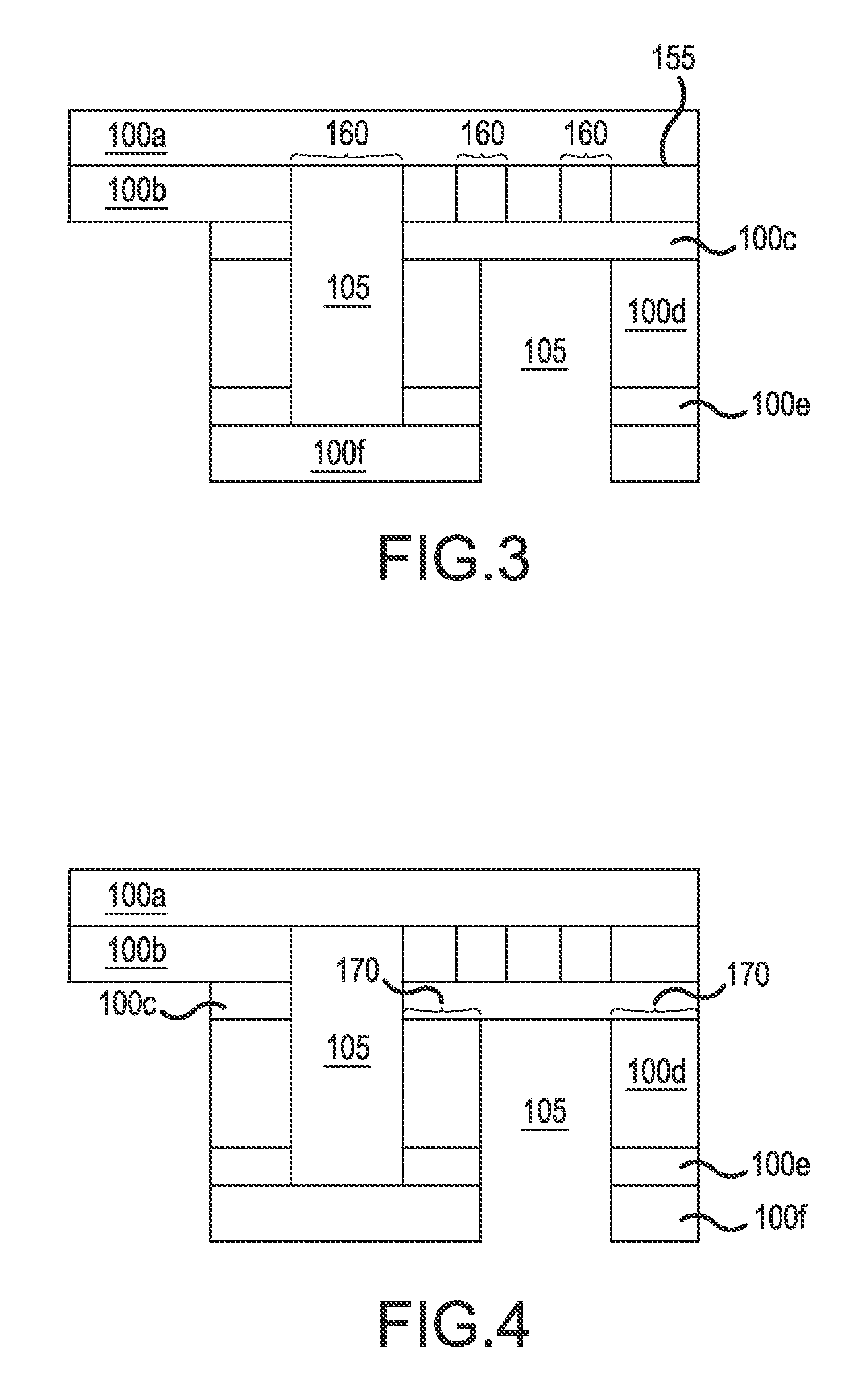
[0038]In the following description of the preferred exemplary embodiments of the present invention, the same or similar reference characters are used for the elements with a similar action and shown in the different drawings, whereby a repeated description of these elements is omitted. Further, the figures in the drawings, the description thereof, and the claims contain numerous features in combination. It is clear in this case to a person skilled in the art that these features can also be considered individually or they can be combined into additional combinations not explicitly described here. Furthermore, the invention in the following description is explained by using different sizes and dimensions, whereby the invention is not to be understood as limited to these sizes and dimensions. If an exemplary embodiment comprises an “and / or” conjunction between a first feature and a second feature, then this can be read such that the exemplary embodiment according to an embodiment has b...


PUM

PropertyMeasurementUnit
distanceaaaaaaaaaa
angleaaaaaaaaaa
distanceaaaaaaaaaa

Abstract

A method for connecting two components in a fluid-tight manner for producing a fluid-tight unit is provided. The method includes a step of providing at least one first component that is solder-plated on one side, wherein the first component has a cutting burr on a side facing away from the solder-plated surface. The method further includes a step of connecting, in particular soldering, the first component to a second component in a fluid-tight manner, in order to produce the fluid-tight unit, wherein the solder-plated surface of the first component faces the second component when connecting the first and second components in a fluid-tight manner.

Description

[0001]This nonprovisional application is a continuation of International Application No. PCT / EP2010 / 059537, which was filed on Jul. 5, 2010, and which claims priority to German Patent Application No. DE 10 2009 032 193.4, which was filed in Germany on Jul. 7, 2009, and which are both herein incorporated by reference.BACKGROUND OF THE INVENTION[0002]1. Field of the Invention[0003]The present invention relates to a method for the fluid-tight connection and a cooling unit.[0004]2. Description of the Background Art[0005]In the field of heat exchanger technology, metal sheets or other components are connected together, particularly soldered, to produce cooling tubes or other heat exchanger components. A composite made of a plurality of metal sheets lying one on top of another, which are connected by soldering into a solid and fluid-tight unit, is suitable for different applications, inter alia, for the production of complex channel or bearing structures for heating or cooling tasks, for ...

Claims


Application Information

Patent Timeline
Patent Type & Authority Patents(United States)
IPC IPC(8): B23K1/20B21D53/04B23P15/26
CPCB23K1/20B21D53/04B23P15/26Y10T29/49366Y10T29/49393F28F9/18
Inventor HECKENBERGER, THOMASHIRSCH, STEFANMOLDOVAN, FLORINFEHRENBACHER, CHRISTOPHHERRMANN, HANS-GEORG
Owner MAHLE BEHR GMBH & CO
Why Eureka
Try Eureka