
Portable oxygen generator

a generator and oxygen technology, applied in respirators, other medical devices, separation processes, etc., can solve the problems of affecting the general environment, affecting the safety of patients, so as to achieve convenient portability or transportation, reduce production costs, and facilitate widespread popularization and application.

Inactive Publication Date: 2015-09-15
LI TEK ELECTRONICS TECH
View PDF6 Cites 0 Cited by
  • Summary
  • Abstract
  • Description
  • Claims
  • Application Information

AI Technical Summary

Benefits of technology

The invention is a portable oxygen generator that is compact, cost-effective, and easy to assemble, carry, and transport. It has a simple structure and a high working efficiency, allowing for cyclic oxygen generation. It also has a light and handy size, making it suitable for family healthcare oxygen therapy, physical exercise, and severe environments. The generator uses a high-nickel alloy material for each component, ensuring durability and reliability. The arrangement of solenoid valves allows for precise gas control, and the integrated pipeline airflow loop type space design reduces the complexity of the airflow conduits outside of the generator. Overall, the invention provides a convenient, efficient, and economical solution for oxygen generation in various settings.

Problems solved by technology

However, relatively speaking, this will also cause many negative effects, of which the heavy damage to the global environment is most obvious.
Nowadays, the external environment is worrying.
However, as the majority of the existing oxygen generators are assembled from ready-made components and have complicated airflow conduits outside, the existing oxygen generators has incompact and huge assembly space.
It is inconvenient for carrying or transportation.
Even the whole cost is influenced so that the price of the existing oxygen generators is still high.

Method used


Image

  • Portable oxygen generator
  • Portable oxygen generator
  • Portable oxygen generator

Examples


Embodiment Construction

[0029]The invention will be further described as below with reference to drawings.

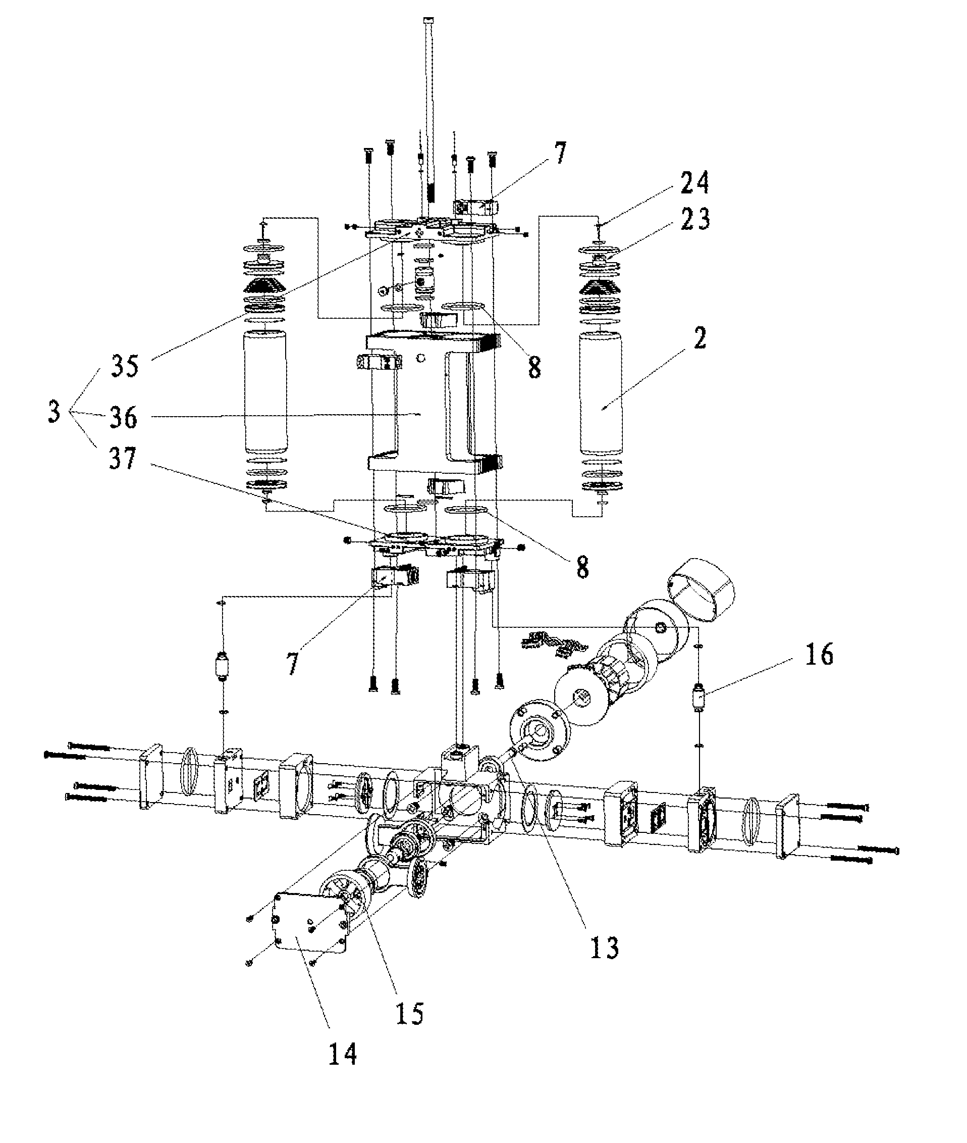
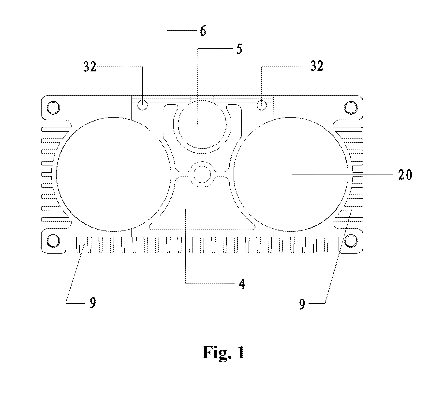
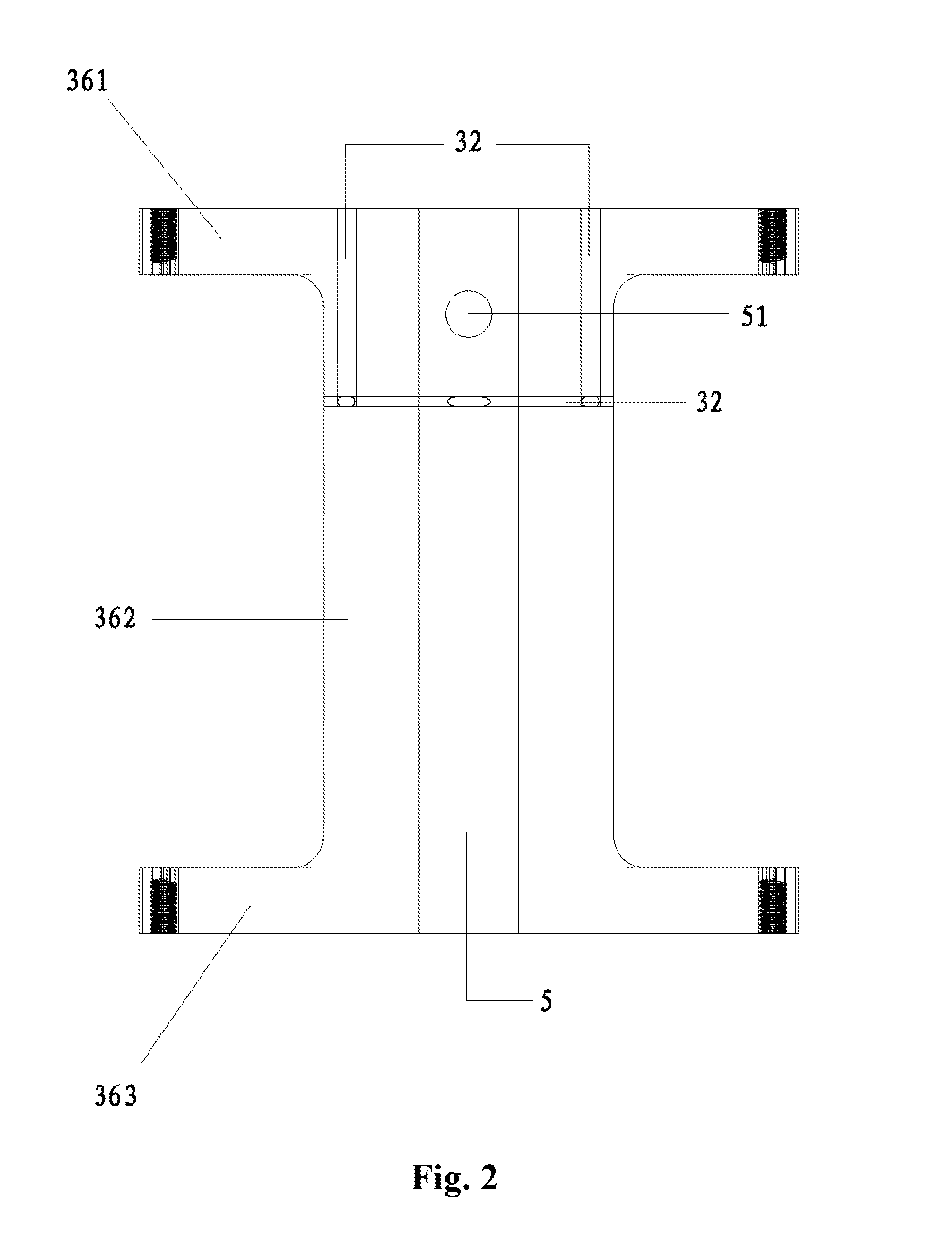
[0030]As shown in FIG. 1 to FIG. 6, a portable oxygen generator of the invention comprises an air pump 1 and a molecular tube 2, and further comprises a molecular seat 3. The molecular tube 2 is detachably fixed on the side wall of the molecular seat 3. The air pump 1 is disposed at the lower part of the molecular seat 3. An air filter bucket 4, an oxygen storage bucket 5 and an exhaust silencing bucket 6 are disposed inside the molecular seat 3. The air filter bucket is provided with an air inlet communicated with the outside air. An air channel 31, an oxygen channel 32 and an exhaust channel 33 are disposed inside the molecular seat 3. The air channel 31 is communicated with the air filter bucket 4, the air pump 1 and the molecular tube 2, respectively. The oxygen channel 32 is communicated with the molecular tube 2 and the oxygen storage bucket 5, respectively. The exhaust channel 33 is communicated...


PUM


Abstract

A portable oxygen generator comprises an air pump, a molecular tube and a molecular seat, the molecular tube is detachably fixed on the side wall of the molecular seat, the air pump is disposed at the lower part of the molecular seat. An air filter bucket, an oxygen storage bucket and an exhaust silencing bucket are disposed inside the molecular seat, the air filter bucket is provided with an air inlet communicated with the outside air. An air channel, an oxygen channel and an exhaust channel are disposed inside the molecular seat, the air channel is respectively communicated with the air filter bucket, the air pump and the molecular tube, the oxygen channel is respectively communicated with the molecular tube and the oxygen storage bucket, the exhaust channel is respectively communicated with the molecular tube and the exhaust silencing bucket, the air channel, the oxygen channel and the exhaust channel are respectively connected with a solenoid valve.

Description

FIELD OF THE INVENTION[0001]The invention relates to the technical field of oxygen generation equipment, in particular to a portable oxygen generator.BACKGROUND OF THE INVENTION[0002]With the development of social civilization and medical technology, researches and controls on diseases are improved prominently, so the life expectancy of human beings increases. As a result, the coming of aging society has become an inevitable trend. However, relatively speaking, this will also cause many negative effects, of which the heavy damage to the global environment is most obvious. For example, sometimes human beings will surfer the counterattack of unknown diseases (for example, SARS) or severe environment (for example, rainstorm or bitter cold, intense heat or earth flow). Nowadays, the external environment is worrying. To reduce the invasion possibility of increasingly severe environment and unknown diseases, human being should make various preparations. As oxygen is an indispensable gas f...

Claims


Application Information

Patent Timeline
Patent Type & Authority Patents(United States)
IPC IPC(8): B01D53/02A61M16/10B01D53/047
CPCB01D53/047A61M16/10A61M2202/0208A61M16/101B01D2256/12B01D2259/402B01D2259/4533B01D2259/4541
Inventor TSENG, WENWEIOUYANG, JASONZHOU, BOBYANG, ZUOWEI, GUIFENG
Owner LI TEK ELECTRONICS TECH
Learn More