Method for cutting a loaf-shaped food using a cutting machine

a cutting machine and loaf technology, applied in the field of cutting bread, can solve the problems of typical failure of vacuum

Inactive Publication Date: 2015-09-15
REIFENHAEUSER UWE
View PDF7 Cites 2 Cited by
  • Summary
  • Abstract
  • Description
  • Claims
  • Application Information

AI Technical Summary

Benefits of technology

[0010]The present invention resolves prior art problems by increasing the safety during the fixing process, such that at least two separate partial suction regions are created, because the vacuum in the at least one other partial suction region is still available if the vacuum in a partial suction region is lost such that at least a residual fixing force for the loaf is still available. The vacuum typically fails due to a rather singular irregularity in the surface consistency of the loaf such that the pressure in the other partial suction region remains intact if a partial suction region develops a leak.
[0013]It is preferred that all partial fixing regions of the surface of the food that are formed by the partial suction regions are acted upon with a negative pressure of the same intensity in order to prevent irregular deformations of the loaf that propagate over its entire length up to the opposite cutting length and can lead to irregular cutting geometries at this location.

Problems solved by technology

The vacuum typically fails due to a rather singular irregularity in the surface consistency of the loaf such that the pressure in the other partial suction region remains intact if a partial suction region develops a leak.

Method used


Image

  • Method for cutting a loaf-shaped food using a cutting machine
  • Method for cutting a loaf-shaped food using a cutting machine
  • Method for cutting a loaf-shaped food using a cutting machine

Examples


Embodiment Construction

[0029]Throughout all the Figures, same or corresponding elements are generally indicated by same reference numerals.

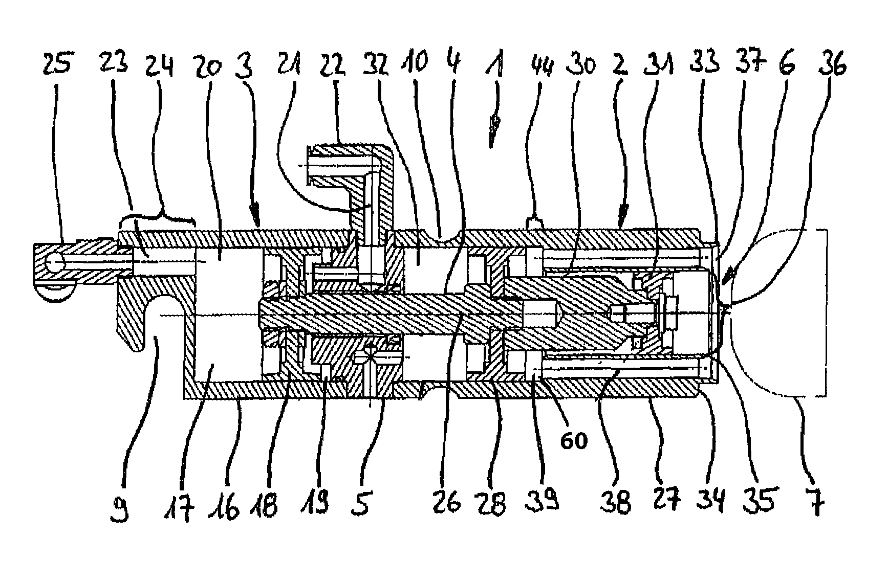
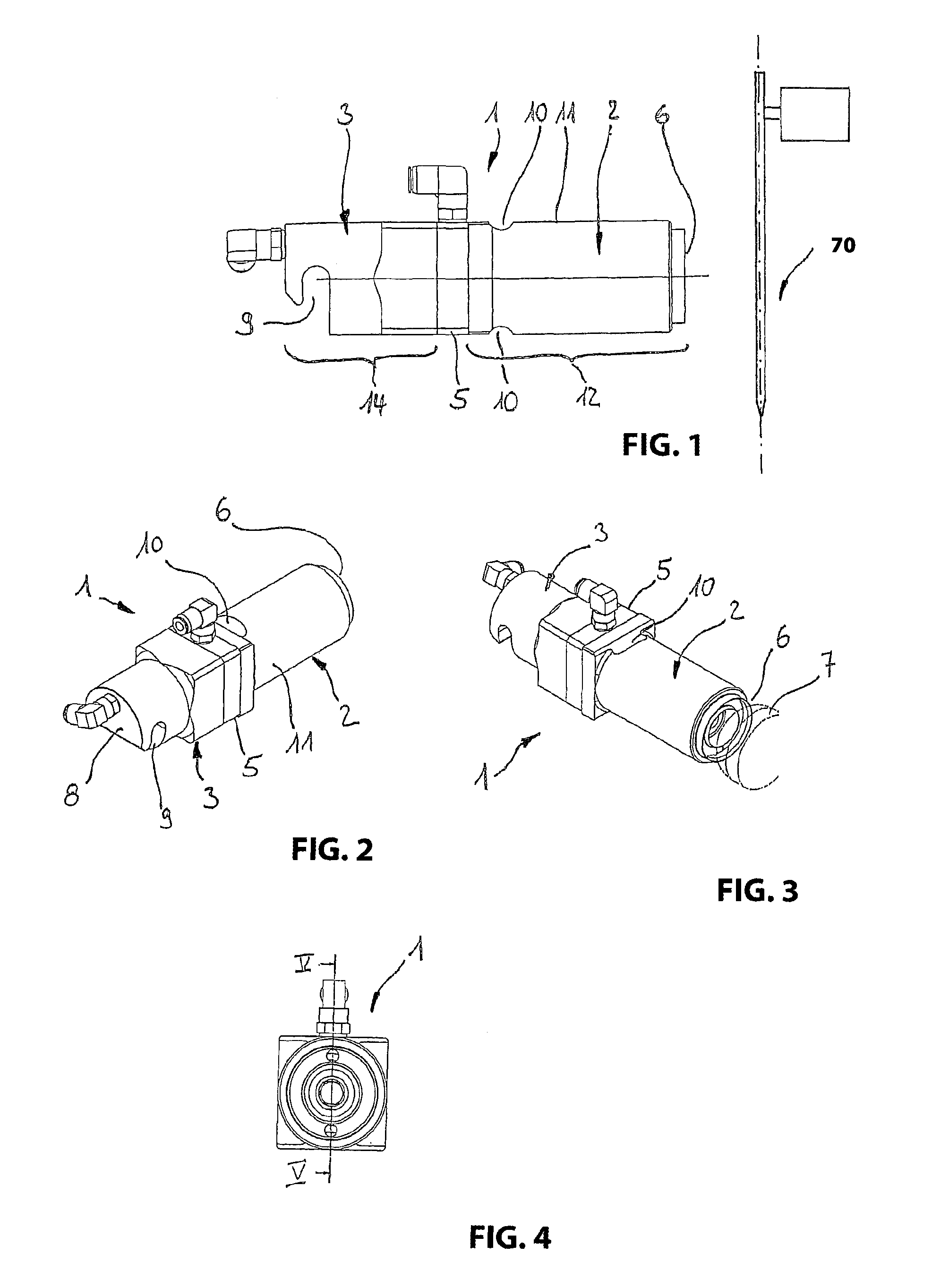
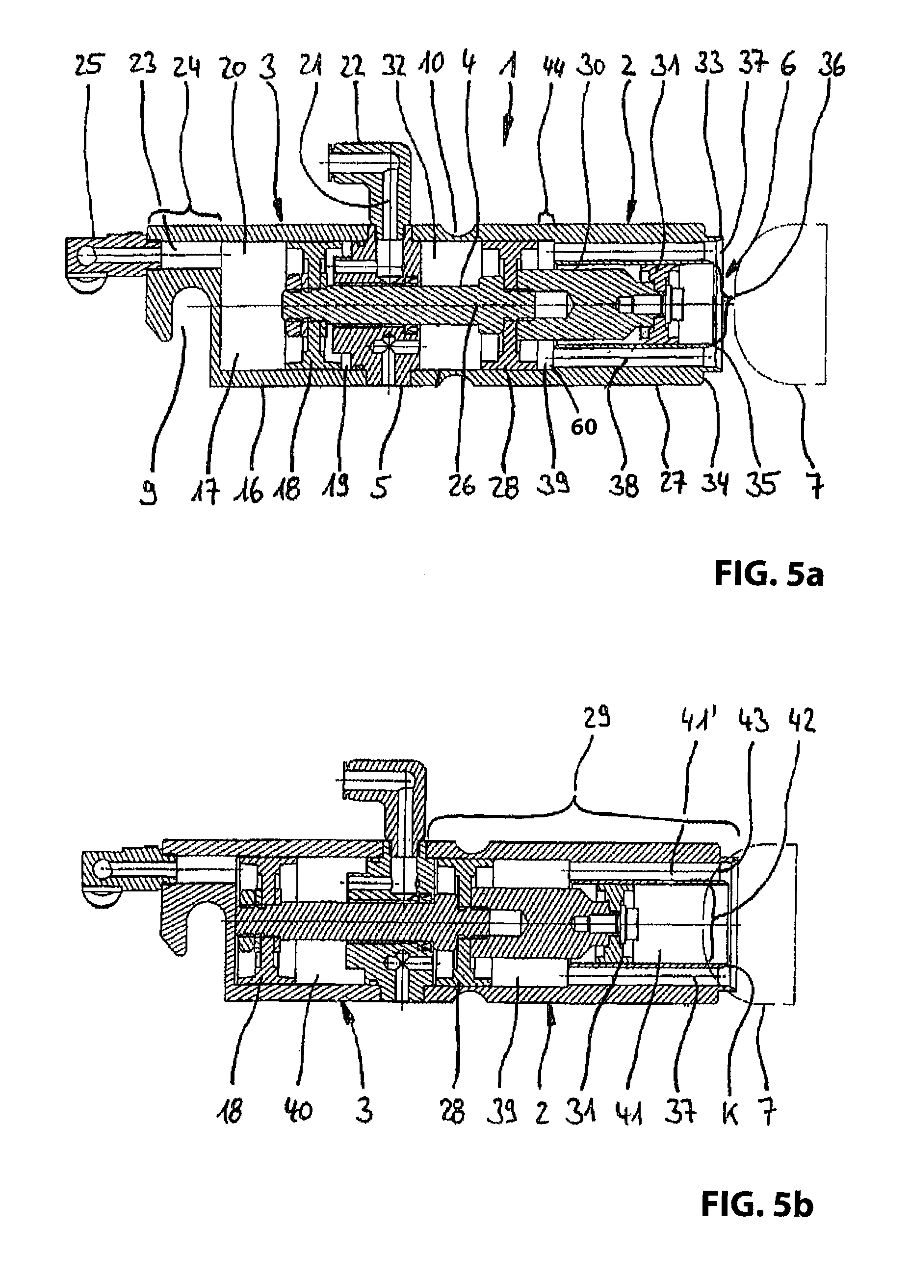
[0030]Turning now to the drawing, and in particular to FIG. 1 to FIG. 5b, there is shown a vacuum gripper 1 consisting of two coaxially arranged piston-cylinder units 2 and 3 that are coupled to one another by means of a common piston rod 4 and separated from one another by a partition wall 5, in which the piston rod 4 is supported in a sliding and sealed fashion.

[0031]The vacuum gripper 1 has a front side 6, to which a product string 7 illustrated in a dashed manner in FIG. 3, for example in the form of a pork sausage, is fixed by means of a vacuum in a manner, which will be described in more detail hereinbelow. On the opposite end, the vacuum gripper 1 has a rear side 8, on which it can be fixed on a base frame 45 of a gripping device that is illustrated in FIGS. 6 to 8 and described in greater detail below with the aid of a slot-shaped recess 9. The mounting is furt...


PUM

PropertyMeasurementUnit
pressureaaaaaaaaaa
elastic propertiesaaaaaaaaaa
suctionaaaaaaaaaa

Abstract

A food loaf is advanced toward a cutting device by a feed apparatus and the loaf is cut into slices, strips or cubes by the cutting device such that the loaf is fixed during the feed movement by a vacuum gripper that is advanced together with the loaf and a negative pressure is generated within an interior of a contact element of the vacuum gripper and acts upon a fixing region of the surface of the loaf in a suction region of the contact element. In order to avoid a vacuum loss, it is proposed that the suction region is divided into at least two separate partial suction regions and the interior of the contact element is accordingly divided into at least two partial interiors, wherein the partial suction regions respectively adjoin one another, are separated from by a contact line and form separate partial fixing regions.

Description

CROSS-REFERENCES TO RELATED APPLICATIONS[0001]This application claims the priority of German Patent Application Serial No. DE 10 2008 011 980.6, filed Feb. 29, 2008 pursuant to 35 U.S.C. 119(a)-(d), the subject matter of which is incorporated herein by reference.BACKGROUND OF THE INVENTION[0002]The invention refers to a method for cutting a food, in particular, a loaf-shaped food, in which a loaf of the food is advanced toward a cutting device by means of a feed apparatus and cut into slices, strips or cubes by said cutting device.[0003]The invention also refers to a cutting machine for cutting a loaf-shaped food that makes it possible to cut a loaf of the food into slices, strips or cubes and features a feed apparatus for advancing the loaf toward the cutting device during the cutting process,[0004]A method and a cutting machine of the above-described type are generally known. As compared to the utilization of gripping hooks, fixing of the loaf by means of a vacuum gripper provides...

Claims


Application Information

Patent Timeline
Patent Type & Authority Patents(United States)
IPC IPC(8): B26D1/01B26D7/01B26D7/06
CPCB26D7/018B26D7/0683B26D2210/02Y10S83/932Y10T83/04Y10T83/0538Y10T83/654Y10T83/6518Y10T83/6657Y10T83/748
Inventor REIFENHAEUSER, UWE
Owner REIFENHAEUSER UWE
Why Eureka
Try Eureka