Supercharge Your Innovation With Domain-Expert AI Agents!

Waste liquid container and liquid consumption apparatus

a technology for liquid consumption apparatus and waste liquid containers, which is applied in the direction of liquid handling, transportation and packaging, packaging goods types, etc., can solve the problems of liquid leakage from the pin, unnecessary load generation, mounting failure, etc., and achieve the effect of simplifying the installation structure with respect to the housing of the cover

Active Publication Date: 2015-09-15
SEIKO EPSON CORP
View PDF46 Cites 6 Cited by
  • Summary
  • Abstract
  • Description
  • Claims
  • Application Information

AI Technical Summary

Benefits of technology

The design effectively suppresses load and mounting failures by guiding the container during insertion and ensuring proper alignment, reducing the risk of liquid leaks and deformation, while facilitating stable electrical connections.

Problems solved by technology

However, in the printer of JP-A-2009-269204, since the pin is provided in the inner side of the waste liquid container mounting portion, the waste liquid tank inserted into the mounting opening is not positioned until the waste liquid tank reaches the inner side in which the pin is engaged to the long hole.
Thereby, the waste liquid tank may be caught in the mounting portion until the long hole reaches the inner side in which the long hole is engaged to the pin after the waste liquid tank is inserted into the mounting portion, and therefore, there is a problem in that an unnecessary load is generated when the water liquid tank is mounted.
In addition, for example, if a position deviation in up and down directions is generated when the waste liquid tank reaches the inner side from the mounting opening, since the pin is not correctly inserted with respect to the long hole of the waste liquid tank, a mounting failure occurs.
Alternatively, there is a problem that a liquid leak from the pin is generated if the pin is loosely inserted into the long hole, or conversely bending of the pin is generated if the pin is forcibly inserted into the long hole.

Method used


Image

  • Waste liquid container and liquid consumption apparatus
  • Waste liquid container and liquid consumption apparatus
  • Waste liquid container and liquid consumption apparatus

Examples


Embodiment Construction

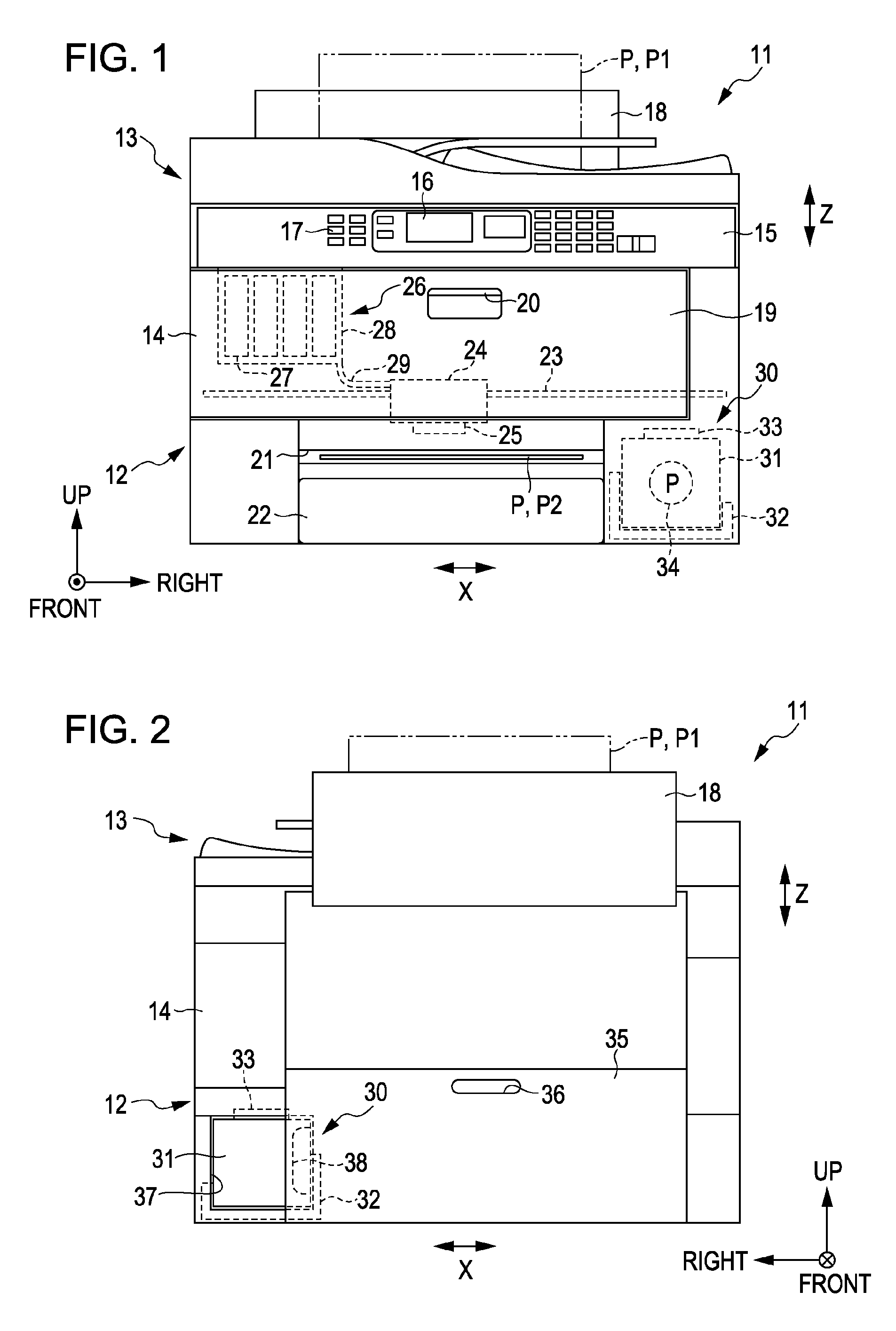
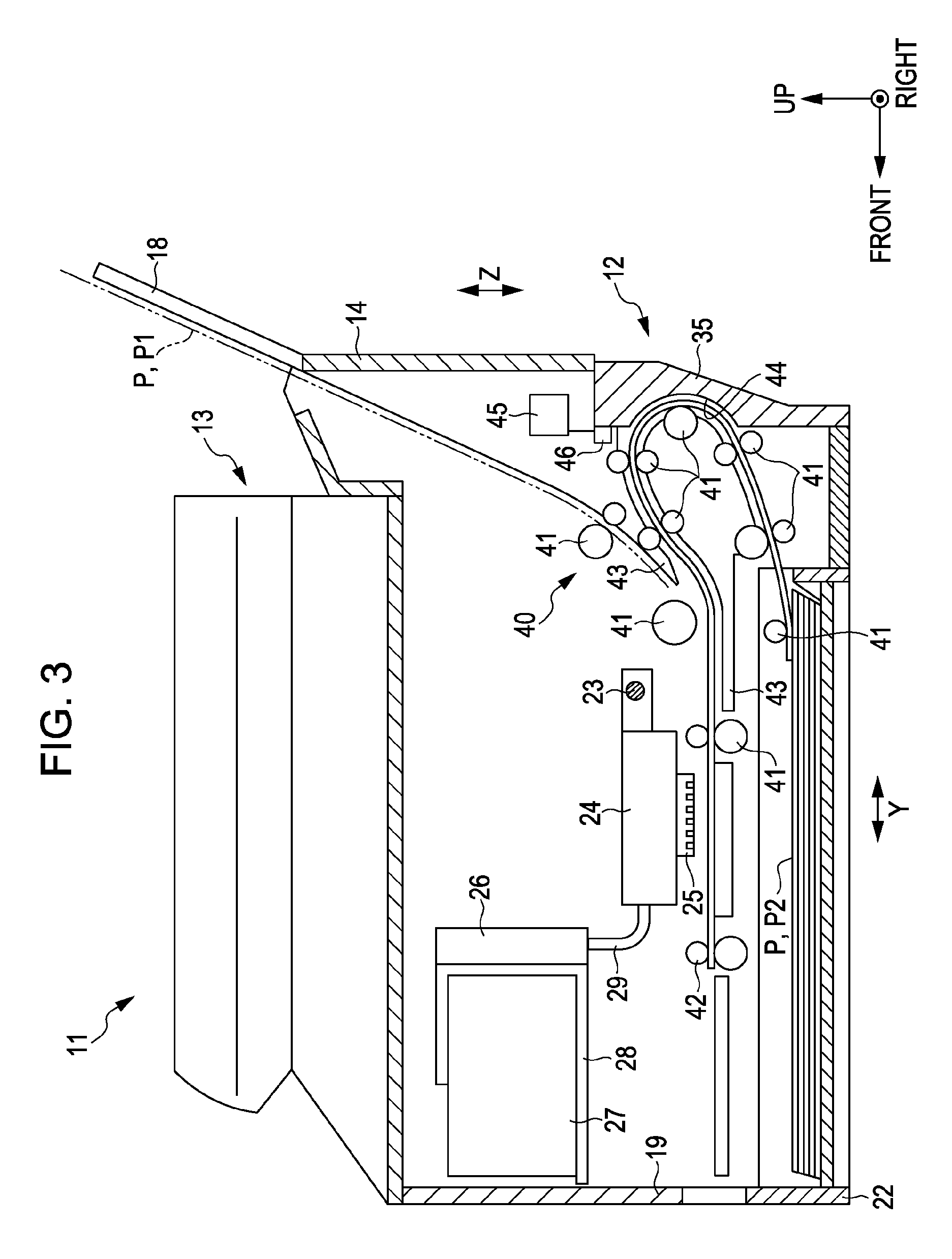
[0113]Hereinafter, an embodiment which embodies the invention as a multifunction machine having a function of an ink jet type printer will be described with reference to drawings. In descriptions below, “front and rear directions”, “right and left directions”, and “up and down directions” each indicate the “front and rear direction”, the “right and left directions”, and the “up and down directions” which are shown by arrows in each drawing. In addition, in arrows which indicate an upper direction, a right direction, and a front direction in drawings, an arrow (the view when the tip of the arrow is viewed from the front) in which a point is depicted in a circle means the arrow which is from the rear of the drawing toward the front thereof, and an arrow (the view when the feathers of the arrow are viewed from the rear) in which a cross is depicted in a circle means the arrow which is from the front of the drawing toward the rear thereof. In addition, the up and down directions becomes...


PUM


Abstract

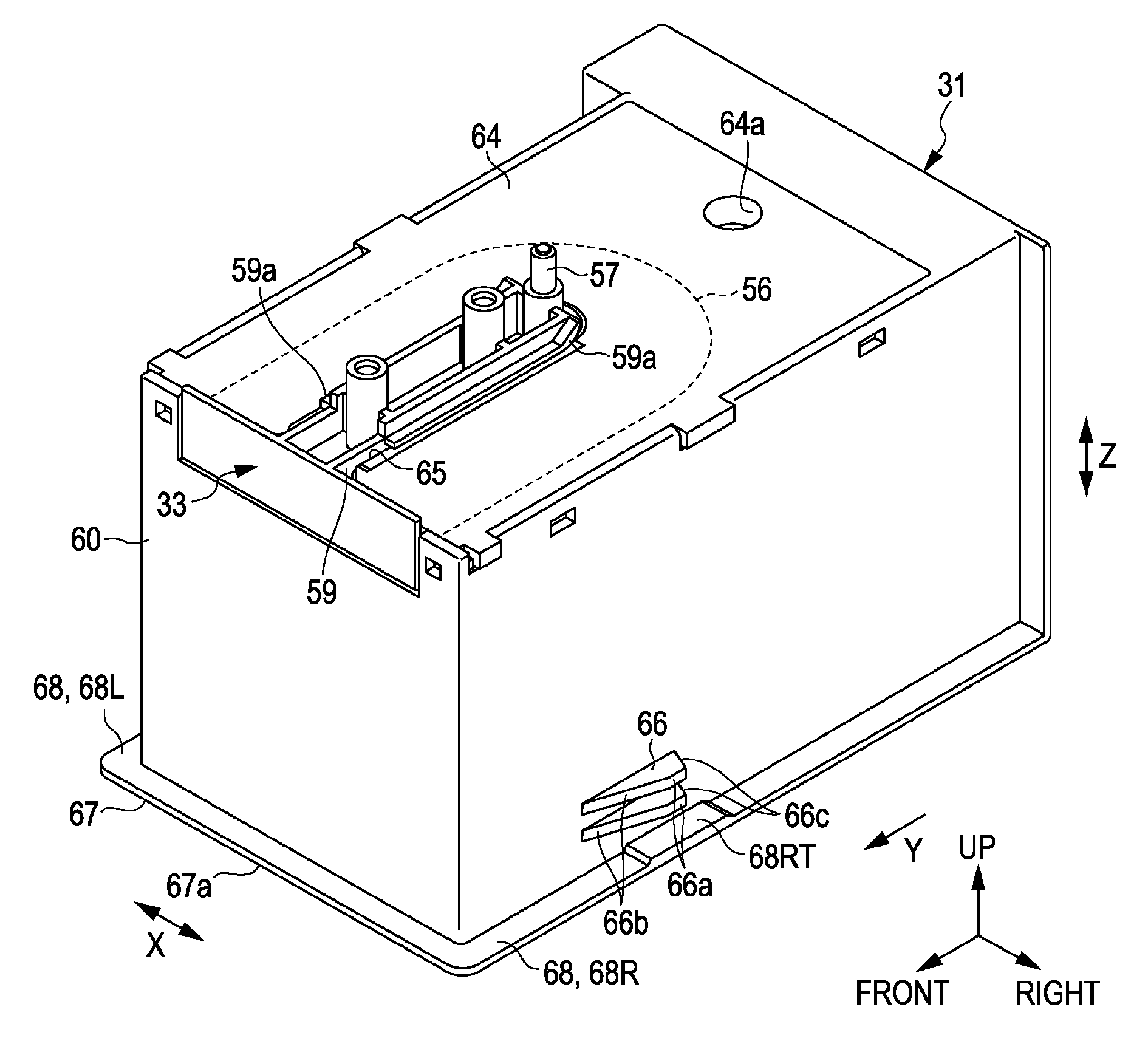
In a waste liquid container which is attachable and detachable to a recording portion including a liquid ejecting head which discharges a waste liquid and can store the waste liquid which is discharged from the liquid ejecting head in a state of being mounted on the recording portion, an engagement portion which protrudes from a side wall of the waste liquid container and is disposed lower in a vertical direction than a guide portion which is provided on the recording portion in the state of being mounted on the recording portion is provided.

Description

CROSS REFERENCES TO RELATED APPLICATIONS[0001]The entire disclosure of Japanese Patent Application Nos. 2011-61176, filed Mar. 18, 2011, 2011-61177, filed Mar. 18, 2011, 2011-61178, filed Mar. 18, 2011, 2011-61179, filed Mar. 18, 2011, 2011-61180, filed Mar. 18, 2011, 2011-61181, filed March 18, and 2011-61182, filed Mar. 18, 2011 are expressly incorporated by reference herein.BACKGROUND[0002]1. Technical Field[0003]The present invention relates to a waste liquid container for storing waste liquid such as waste ink and, a liquid consumption apparatus and a liquid ejecting apparatus which include the waste liquid container.[0004]2. Related Art[0005]As a liquid consumption apparatus which consumes liquid by ejecting the liquid with respect to a target such as a sheet, an ink jet type printer is widely known. In the related art, in the above-described printer, there is a printer that includes a waste liquid container mounting portion on which a waste liquid tank (waste liquid container...

Claims


Application Information

Patent Timeline
Patent Type & Authority Patents(United States)
IPC IPC(8): B41J2/165B41J2/17
CPCB41J2/1721B41J2002/1728B41J2/1728
Inventor HARADA, SHUHEINAKATA, MASANORIYAMAMOTO, TAISUKE
Owner SEIKO EPSON CORP
Features
  • R&D
  • Intellectual Property
  • Life Sciences
  • Materials
  • Tech Scout
  • Unparalleled Data Quality
  • Higher Quality Content
  • 60% Fewer Hallucinations
Learn More