System and devices for collecting and treating waste water from engine washing

a jet engine and waste water technology, applied in the direction of machines/engines, separation with moving sorbents, construction, etc., can solve the problems of reducing engine performance, changing the aerodynamic properties of the engine, and consuming large quantities of air, so as to achieve simple process, enhance wash results, and limit success

Active Publication Date: 2007-11-20
ECOSERVICES
View PDF113 Cites 49 Cited by
  • Summary
  • Abstract
  • Description
  • Claims
  • Application Information

AI Technical Summary

Benefits of technology

[0020]The solution according to the present invention provides several advantages over the existing solutions. One advantage is that hazardous particles, substances, or other types of content, such as released fouling material, combustion solids, compressor and turbine coating material, heavy metals and oil and fat products, can be removed or separated from the waste liquid resulting from a washing operation in an efficient and environmentally friendly manner
[0021]Another advantage is the inventive devices and systems can be used with different types and designs of gas turbine aircraft engines, such as turbojets, turboprop, turbo-shaft and mixed or un-mixed turbofan engines, and, moreover, with different aircraft types and designs from different manufactures because the devices and systems can be accurately adjusted to a specific engine or aircraft. Accordingly, the present invention provides for a very high degree of flexibility since one system can be used for all types of engines and aircrafts, i.e. the present invention provides for a collecting and treating of waste wash liquid generally applicable to most winged aircraft. This also entails cost savings because one and the same system or mobile cart including the system can be used for all types of engines and aircrafts.
[0022]A further advantage is that there is no physical contact between the collector device and the engine, which entails that any damages of the engines can be avoided.

Problems solved by technology

Air breathing machines like jet engines consume large quantities of air.
However, there are particles with properties of sticking on to components in the engine's gas path changing the aerodynamic properties of the engine and more particularly reducing engine performance.
The contaminants sticking on to components in the engine gas path cause fouling of the engine.
The consequence of gas path fouling is an engine operating less efficient.
With the reduction in efficiency follows that the engine is less economic to operate and has higher emissions.
Fouling will result in more fuel having to be burnt for achieving the same thrust as for the clean engine.
Further, an environmental drawback is found with the higher fuel consumption in form of increased carbon dioxide emissions.
In addition, more fuel being burnt results in higher temperatures in the engine's combustor.
The higher temperature exposures will shorten the life time of the engine.
The higher firing temperature results in increased formation of NOx which is yet another environmental drawback.
In summary, the operator of a fouled engine suffers from reduced engine lifetime, unfavourable operating economics and higher emissions.
However, this method has limited success due to the simple nature of the process.
This waste liquid may be hazardous.
Cadmium is environmentally very sensitive and can not be allowed to be disposed to the effluent.
The large combined possibility of engines on aircraft types and from different aircraft manufacturers result in a practical problem in designing a system for collecting and treating of waste wash liquid that is generally applicable to most winged aircraft.
However, any operation resulting in anything being hooked on to an engine has the disadvantage that it may be subject to engine damage

Method used


Image

  • System and devices for collecting and treating waste water from engine washing
  • System and devices for collecting and treating waste water from engine washing
  • System and devices for collecting and treating waste water from engine washing

Examples


Embodiment Construction

[0034]Further scope of applicability of the present invention will become apparent from the detailed description given hereinafter. However, it should be understood that the detailed description and specific examples, while indicating preferred embodiments of the invention, are given by way of illustration only, since various changes and modifications within the spirit and scope of the invention will become apparent to those skilled in the art from this detailed description.

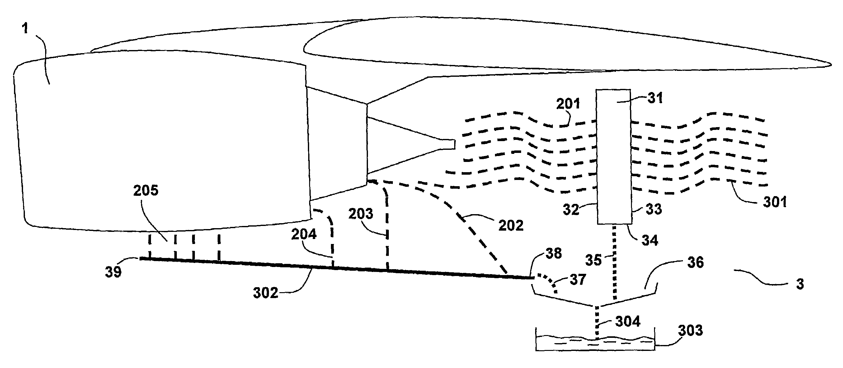
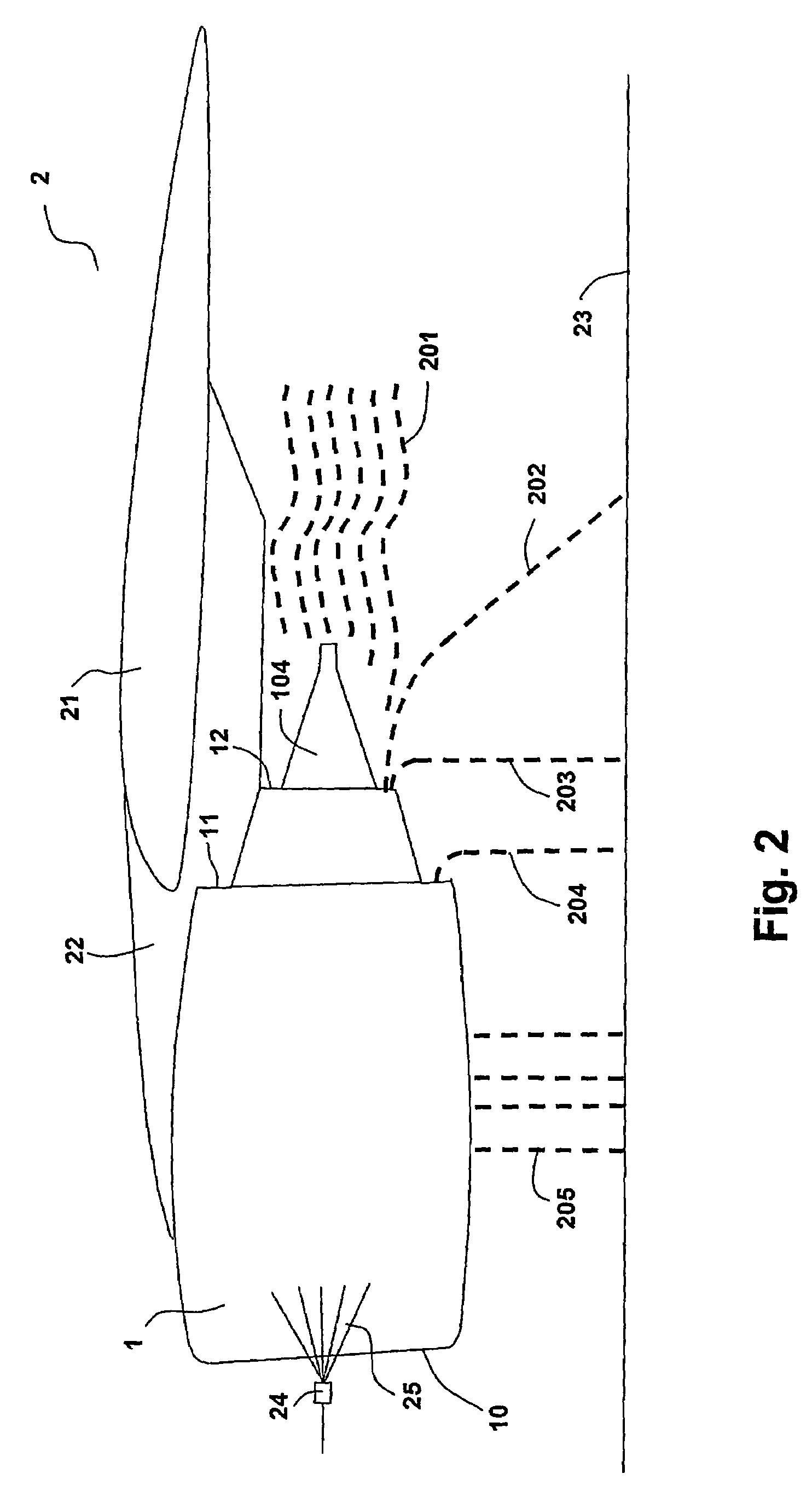
[0035]The invention can be practised on several engine types such as turboshaft, turboprop, turbojet and mixed / un-mixed multi shaft turbo fan engines. The invention can be practised on under-wing mounted engines as well as tail mounted engines as further shown in FIG. 6 and FIG. 7.

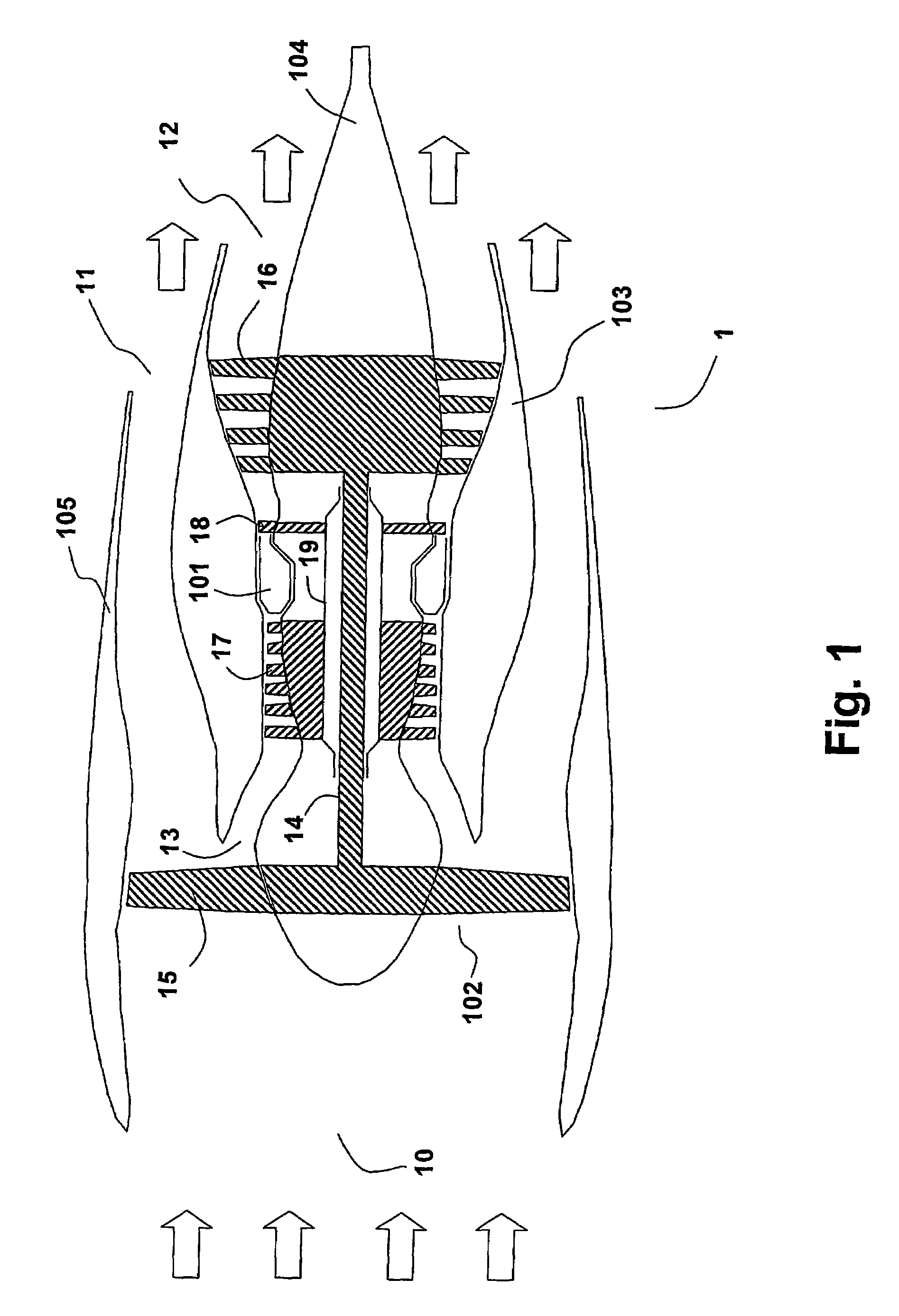
[0036]FIG. 1 shows a cross section of an un-mixed turbofan engine. This engine is of a common type found on e.g. large aircraft in passenger service. Engine 1 comprises of a fan section 102 and a core engine section 103. Air flows are i...


PUM

PropertyMeasurementUnit
sizeaaaaaaaaaa
sizeaaaaaaaaaa
volumeaaaaaaaaaa

Abstract

A system and method for washing engines and for collecting and treating the waste water from engine washing operations. The system includes a collecting device for collecting waste liquid during a washing operation of the engine and a treatment device for treating waste liquid collected during the washing operation. The system may be advantageously arranged on a mobile cart having a chassis provided with wheels. The mobile cart also includes an adjusting device for adjusting the vertical position of liquid separating and collecting components relative to the engine.

Description

[0001]This is a nationalization of PCT / SE04 / 000922 filed Jun. 14, 2004 and published in English.TECHNICAL FIELD[0002]The present invention generally relates to the field of washing jet engines, particularly using washing liquids such as water and detergent or water only, and more specifically to a system, and devices for collecting and treating the waste water from engine washing operations and a mobile cart comprising such a system.BACKGROUND OF THE INVENTION[0003]A gas turbine engine installed as an aircraft engine comprises a compressor compressing ambient air, a combustor burning fuel together with the compressed air and a turbine for driving the compressor. The expanding combustion gases drive the turbine and also result in thrust used for propelling the aircraft.[0004]Air breathing machines like jet engines consume large quantities of air. Air contains foreign particles in form of aerosols or larger particles which then enters the engine with the air stream. The majority of th...

Claims


Application Information

Patent Timeline
Patent Type & Authority Patents(United States)
IPC IPC(8): B08B3/02B08B3/14B08B5/02B08B9/032B01DB01D19/00B01D35/01B08B3/08B64F5/00C02F1/00F01D25/00F02C7/00
CPCB08B3/02F01D25/002B08B9/00B08B3/08F02C7/00B64F5/00B08B3/026B60S3/044B05B7/0093B05B7/166B05B7/26B08B3/003B08B3/10B08B9/093E03B1/042F05D2220/323
Inventor HJERPE, CARL-JOHANASPLUND, PETER
Owner ECOSERVICES
Why Eureka
Try Eureka