Hydraulic excavator

a hydraulic excavator and hydraulic technology, applied in the field of hydraulic excavators, can solve the problems of inability to accurately install, deflecting supporting objects, and increasing the load on the bracket for attaching the exhaust processing device to the engine, so as to reduce the load on the first connecting pipe, reduce the enlargement of the hydraulic excavator, and improve the freedom of disposing the diesel particulate filter device and the selective catalytic reduction device in the horizontal direction.

Active Publication Date: 2015-09-15
KOMATSU LTD
View PDF43 Cites 5 Cited by
  • Summary
  • Abstract
  • Description
  • Claims
  • Application Information

AI Technical Summary

Benefits of technology

[0009]The diesel particulate filter device requires a high frequency of maintenance compared to the selective catalytic reduction device due to the collection of particulate matter in the exhaust gas. During maintenance, the diesel particulate filter device is removed from the vehicle. At this time, a connecting pipe may interfere with the diesel particulate filter device depending on the position of the connecting pipe. In this case, it becomes difficult to remove the diesel particulate filter device from the vehicle and maintenance performance is reduced.
[0042]In the hydraulic excavator according to the fifteenth embodiment of the present invention, the bellows part is located lower than the beam member. As a result, the diesel particulate filter device and the selective catalytic reduction device can be disposed in a lower location. Consequently, enlargement of the hydraulic excavator can be suppressed.

Problems solved by technology

Consequently, a load on a bracket for attaching the exhaust processing device to the engine becomes larger.
When the exhaust processing device is supported by a supporting object other than the engine as described in the above Japan Patent Laid-open Patent Publication 2012-097413, there is a possibility that the supporting object may deflect due to the weight of the exhaust processing device.
As a result, installation inaccuracies occur when connecting the exhaust processing device and the engine.
Consequently, connecting the engine and the exhaust processing device may become difficult.
The diesel particulate filter device requires a high frequency of maintenance compared to the selective catalytic reduction device due to the collection of particulate matter in the exhaust gas.
At this time, a connecting pipe may interfere with the diesel particulate filter device depending on the position of the connecting pipe.
In this case, it becomes difficult to remove the diesel particulate filter device from the vehicle and maintenance performance is reduced.
As a result, installation inaccuracies that occur when connecting the diesel particulate filter device and the engine can be absorbed even if the vehicle body frame deflects due to the weight of the diesel particulate filter device.

Method used


Image

  • Hydraulic excavator
  • Hydraulic excavator
  • Hydraulic excavator

Examples


Embodiment Construction

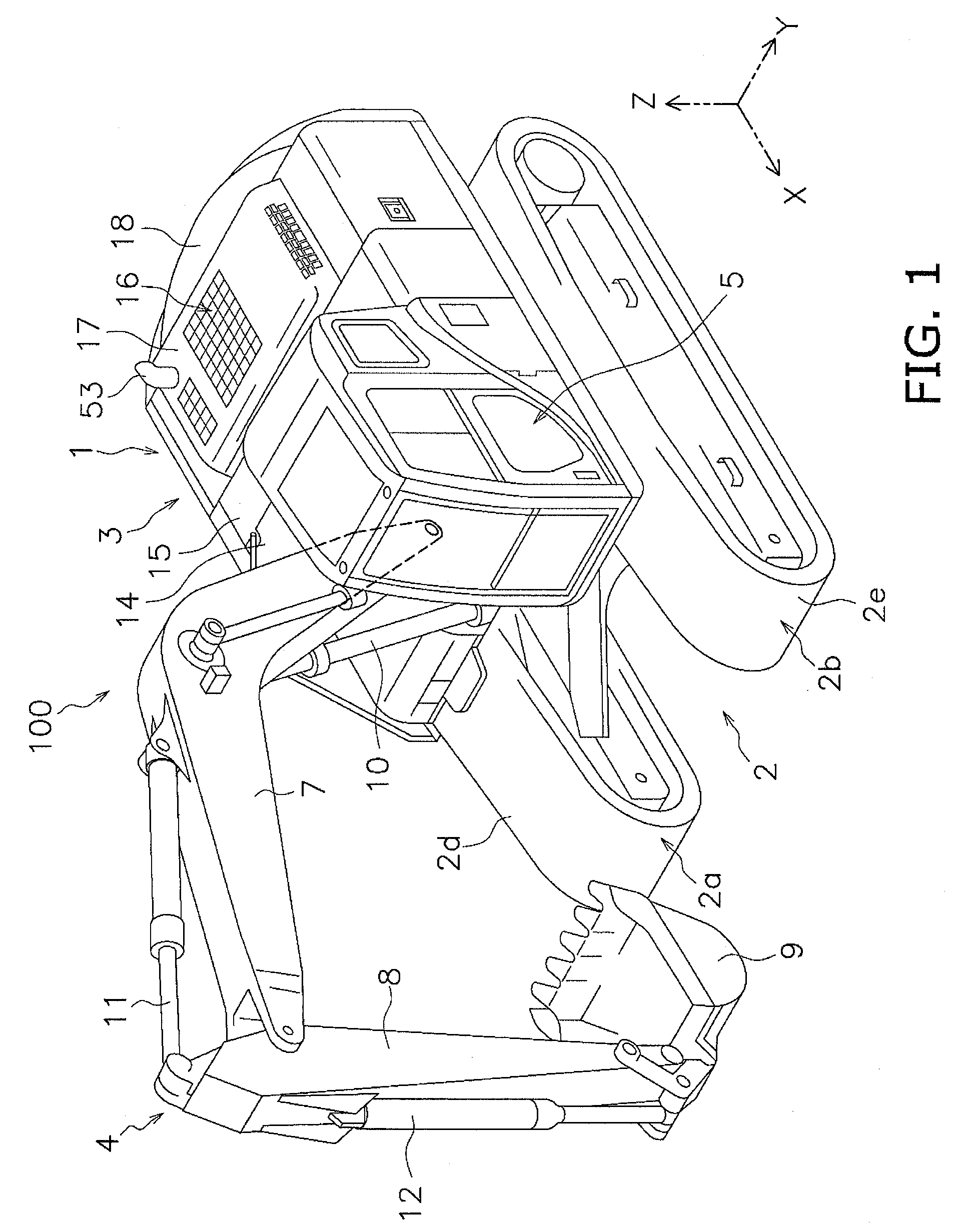
[0047]FIG. 1 illustrates a hydraulic excavator 100 according to the first embodiment of the present invention. The hydraulic excavator 100 is equipped with a vehicle body 1 and working implement 4.

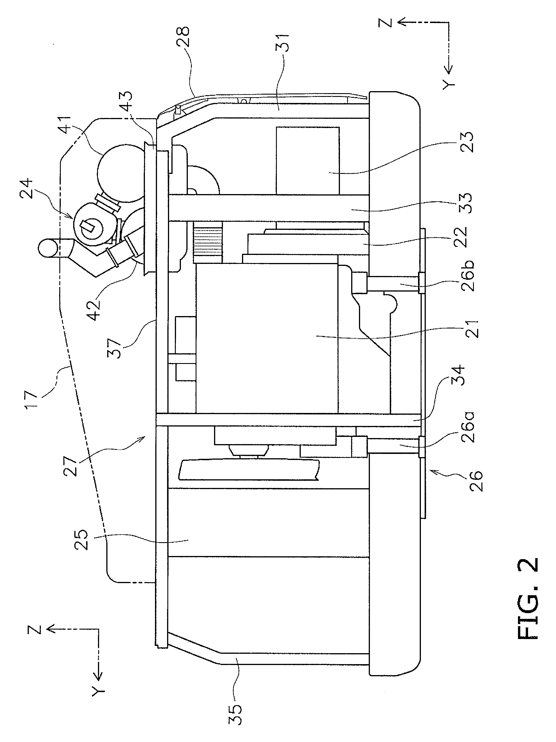
[0048]The vehicle body 1 includes a traveling unit 2 and a revolving unit 3. The traveling unit 2 includes a pair of travel devices 2a and 2b. The travel devices 2a and 2b respectively include crawlers 2d and 2e. The travel devices 2a and 2b allow the hydraulic excavator 100 to travel due to the crawlers 2d and 2e being driven by driving power from a belowmentioned engine 21 (see FIG. 2).

[0049]The front-back direction in the following explanation signifies the front-back direction of the vehicle body 1. In other words, the front-back direction is the direction of the front and back as seen by an operator sitting in an operating cabin 5. The right-left direction or the lateral direction signifies the vehicle width direction of the vehicle body 1. In other words, the right-left direction, th...


PUM


Abstract

A hydraulic excavator includes an engine, a revolving frame supporting the engine, a vehicle body frame, a diesel particulate filter device, and a first connecting pipe. The vehicle body frame is disposed on the revolving frame. The diesel particulate filter device and the selective catalytic reduction device are supported by the vehicle body frame. The first connecting pipe connects the engine and the diesel particulate filter device. The first connecting pipe includes a bellows part that is extendable in at least a portion thereof. The diesel particulate filter device is located further away from the engine than the selective catalytic reduction device. The first connecting pipe passes below the selective catalytic reduction device and is connected to the diesel particulate filter device. A connecting portion for the diesel particulate filter device and the first connecting pipe is located below the diesel particulate filter device.

Description

CROSS-REFERENCE TO RELATED APPLICATIONS[0001]This application is a U.S. National stage application of International Application No. PCT / JP2012 / 080011, filed on Nov. 20, 2012. This U.S. National stage application claims priority under 35 U.S.C. §119(a) to Japanese Patent Application No. 2012-228795, filed in Japan on Oct. 16, 2012, the entire contents of which are hereby incorporated herein by reference.BACKGROUND[0002]1. Field of the Invention[0003]The present invention relates to a hydraulic excavator.[0004]2. Background Information[0005]A hydraulic excavator is equipped with an exhaust processing device. An exhaust processing device is connected to an engine through a connection pipe (exhaust pipe) for processing exhaust from the engine. The exhaust processing device includes a diesel particulate filter device and a selective catalytic reduction device. The diesel particulate filter device reduces particulate matter in the exhaust. The selective catalytic reduction device reduces ...

Claims


Application Information

Patent Timeline
Patent Type & Authority Patents(United States)
IPC IPC(8): F01N13/00E02F9/08F01N13/08F01N3/021
CPCE02F9/0866F01N3/021F01N13/009F01N13/08F01N2590/08Y02T10/20Y02T10/12Y02A50/20
Inventor MORI, TADASHIHIMOTO, MANABUNISHIMURA, OSAMUSANADA, KENJI
Owner KOMATSU LTD
Why Eureka
Try Eureka