Textile industry steam generation equipment

A technology for generating equipment and textile industry, applied in the field of steam generating equipment in the textile industry, can solve the problems of reduced work efficiency and unrealized steam, etc., and achieve the effects of improving work efficiency, solving the combustion process, and being convenient to operate.

Active Publication Date: 2020-04-17
SHANDONG LICHANG TEXTILE TECH
View PDF6 Cites 0 Cited by
  • Summary
  • Abstract
  • Description
  • Claims
  • Application Information

AI Technical Summary

Problems solved by technology

[0004] The above scheme has not yet realized the process of burning the dye to generate steam with a lower cost method, which reduces the work efficiency

Method used


Image

  • Textile industry steam generation equipment
  • Textile industry steam generation equipment
  • Textile industry steam generation equipment

Examples


Embodiment Construction

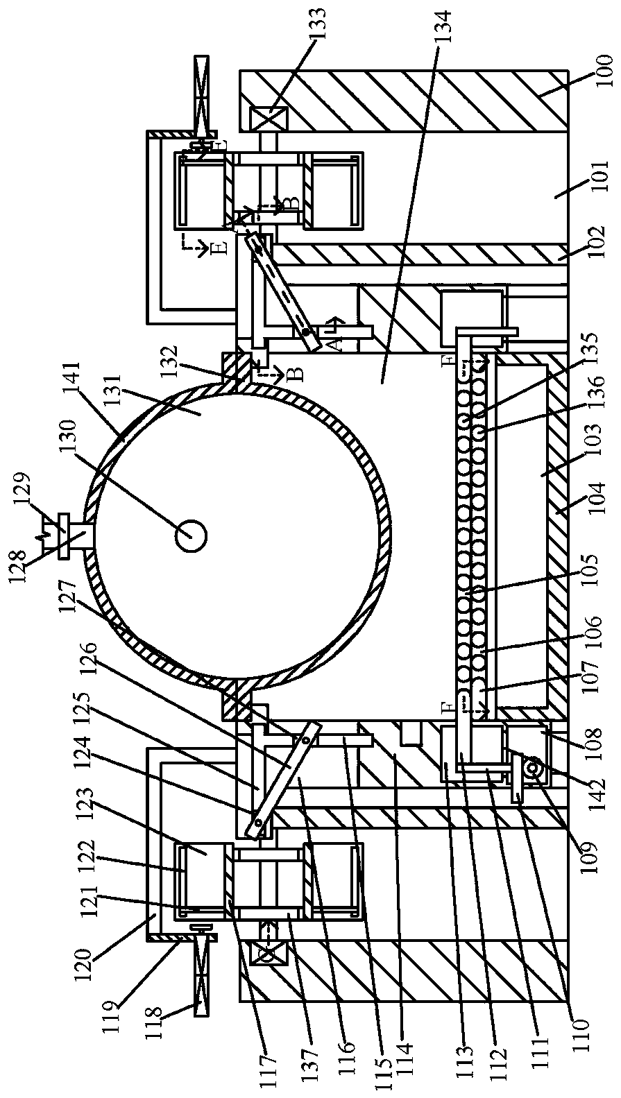
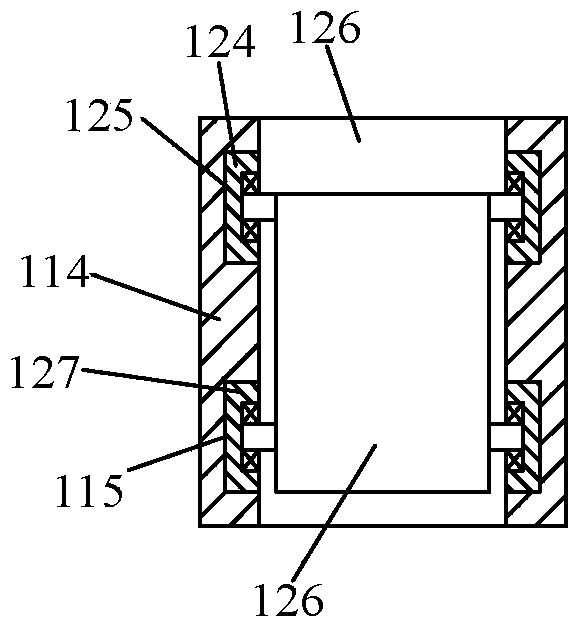
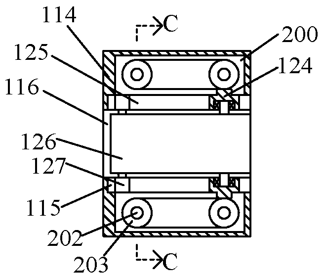
[0023] Combine below Figure 1-8 The present invention will be described in detail.

[0024] Reference Figure 1-8 , According to an embodiment of the present invention, a steam generating equipment for the textile industry includes a box body 114, a discharge device, a pushing device, a cylinder device, a boiler device, and a discharge device. The box body 114 is fixedly provided with a combustion opening facing upwards. The depth of the combustion chamber 134 is 80cm. The left end wall of the combustion chamber 134 is fixedly provided with a drive sprocket 137. The left and right end walls of the combustion chamber 134 are connected with a sliding cavity 116. The sliding cavity 116 is arranged symmetrically. A discharging device is arranged in the cavity 116, a cavity 113 in the box 114 is arranged under the sliding cavity 116, and a transmission cavity 108 in the box 114 is arranged under the cavity 113 on the left, the transmission cavity 108 and the container A connecting ...


PUM


Abstract

The invention discloses textile industry steam generation equipment. The textile industry steam generation equipment comprises a box body, emptying devices, a pushing device, an air cylinder device, aboiler device and a discharging device, wherein a combustion cavity with an upward opening is fixedly formed in the box body, a driving chain wheel is fixedly arranged on the left end wall of the combustion cavity, sliding cavities are formed in the left end wall and the right end wall of the combustion cavity in a communicating mode, and the sliding cavities are formed in a bilateral symmetry mode, the emptying devices are arranged in the sliding cavities, containing cavities located in the box body are formed below the sliding cavities, and a transmission cavity located in the box body is formed below the containing cavity in the left side. The textile industry steam generation equipment is simple in the structure and convenient to operate, by means of the emptying devices, the pushingdevice, the air cylinder device, the boiler device and the discharging device, the equipment achieves the process that biomass fuel is combusted to heat water liquid into high-temperature water vapor,more smart structures are applied in the process, the unexpected technical effect is achieved, and the working efficiency of the equipment is improved.

Description

Technical field [0001] The invention relates to the technical field of textile industry equipment, in particular to a textile industry steam generation equipment. Background technique [0002] The disadvantage of the prior art is that steam needs to be used to dry and remove dampness on the textile during the textile processing process. In this process, the steam needs to be generated by specific equipment. The traditional steam generation equipment is often driven by electric energy. Consumption increases the operating cost of the plant, and at this time a lower-cost steam generating device is needed to replace the traditional steam generating device. To this end, people have carried out long-term exploration and put forward various solutions. [0003] For example, the Chinese patent document steam generating device and steam cleaning equipment discloses [application number: 201710295689.9], including a water storage unit and a combustion unit. The combustion unit is connected t...

Claims


Application Information

Patent Timeline
Patent Type & Authority Applications(China)
IPC IPC(8): F22B31/00
CPCF22B31/00
Inventor 张鑫罗诚郑素文
Owner SHANDONG LICHANG TEXTILE TECH
Why Eureka
Try Eureka