System and method for calibrating video and lidar subsystems

a subsystem and video camera technology, applied in the field of video and lidar subsystem calibration, can solve the problems of difficult to obtain accurate three-dimensional (3d) images of targets using a two-dimensional (2d) video camera subsystem integrated with a three-dimensional lidar (laser radar) subsystem

Active Publication Date: 2015-09-15
AEVA INC
View PDF2 Cites 114 Cited by
  • Summary
  • Abstract
  • Description
  • Claims
  • Application Information

AI Technical Summary

Problems solved by technology

Obtaining accurate three-dimensional (3D) images of a target using a two-dimensional (2D) video camera subsystem integrated with a three-dimensional lidar (laser radar) subsystem is difficult unless the two subsystems are calibrated with one another.

Method used


Image

  • System and method for calibrating video and lidar subsystems
  • System and method for calibrating video and lidar subsystems
  • System and method for calibrating video and lidar subsystems

Examples


Embodiment Construction

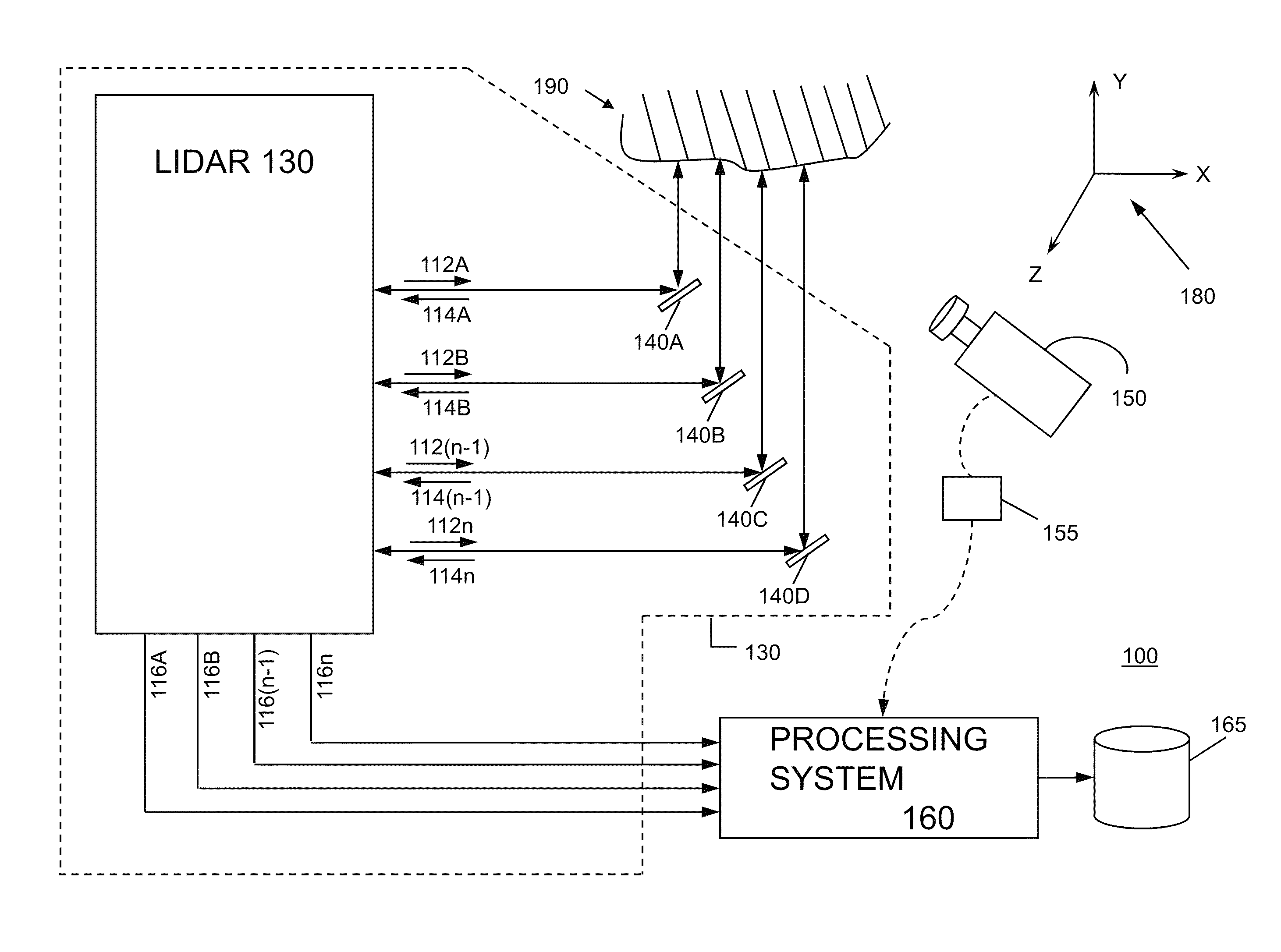
[0024]FIG. 1 illustrates a combined lidar and video camera system 100 (or three-dimensional measurement system 100) according to various implementations of the invention. Various implementations of the invention utilize synergies between lidar measurements and video images to resolve six degrees of freedom for motion of a target to a degree not otherwise possible with either a lidar or video camera alone.

[0025]Combined system 100 includes a lidar subsystem 130, a video subsystem 150, and a processing system 160. As illustrated, lidar subsystem 130 includes two or more lidar beam outputs 112 (illustrated as a beam 112A, a beam 112B, a beam 112(n−1), and a beam 112n); two or more reflected beam inputs 114 each corresponding to one of beams 112 (illustrated as a reflected beam 114A, a reflected beam 1146, a reflected beam 114(n−1), and a reflected beam 114n); two or more lidar outputs 116 each associated with a pair of beam 112 / reflected beam 114 (illustrated as a lidar output 116A ass...


PUM


Abstract

A system uses range and Doppler velocity measurements from a lidar system and images from a video system to estimate a six degree-of-freedom trajectory of a target. The system calibrates the lidar subsystem with the video subsystem in two stages. In a first stage, the system calibrates the lidar subsystem so that lidar measurements provide 3D lidar coordinates. In a second stage, the system relates the 3D lidar coordinates with a video image obtained from the video subsystem.

Description

CROSS-REFERENCE TO RELATED APPLICATIONS[0001]This application claims priority to U.S. Provisional Patent Application No. 61 / 682,463, which was filed on Aug. 13, 2012, and is incorporated herein by reference as if reproduced below in its entirety.FIELD OF THE INVENTION[0002]The invention is generally related to calibrating video and lidar subsystems and more particularly, to calibrating the video and lidar subsystems to obtain accurate three-dimensional (3D) images of a target.BACKGROUND OF THE INVENTION[0003]Obtaining accurate three-dimensional (3D) images of a target using a two-dimensional (2D) video camera subsystem integrated with a three-dimensional lidar (laser radar) subsystem is difficult unless the two subsystems are calibrated with one another. Calibration may refer to the registration of the two subsystems such that points on a surface of a target are accurately mapped to one another by each of the two subsystems (or substantially so within the measurement tolerances, etc...

Claims


Application Information

Patent Timeline
Patent Type & Authority Patents(United States)
IPC IPC(8): G01S7/497G01S17/02G01S17/58G01S17/34G01S17/86
CPCG01S7/497G01S17/023G01S17/58G01S7/4972G01S17/86G01S17/34
Inventor SEBASTIAN, RICHARD L.ZHELEZNYAK, ANATOLEY T.
Owner AEVA INC
Why Eureka
Try Eureka