Ultrasonic imaging apparatus and a method for generating an ultrasonic image

a technology of ultrasonic imaging and ultrasonic imaging, which is applied in the field of ultrasonic imaging apparatus and a generation method of ultrasonic images, can solve the problems of time lag, cumbersome adjustment of doppler velocity range (prf) and velocity offset (bls), and difficult observation

Active Publication Date: 2009-04-02
TOSHIBA MEDICAL SYST CORP
View PDF12 Cites 23 Cited by
  • Summary
  • Abstract
  • Description
  • Claims
  • Application Information

AI Technical Summary

Benefits of technology

[0015]In the first aspect of the present invention, a desired Doppler velocity range is designated on the Doppler spectrum image displayed on the display, and a resampling process and frequency analysis are executed on the received signals stored in the storage in accordance with the sampling frequency corresponding to the designated Doppler velocity range. Consequently, it becomes possible to display a Doppler spectrum image with a desired Doppler velocity range without deteriorating the temporal resolution and frequency decomposition.

Problems solved by technology

Such a Doppler waveform displayed small makes observation difficult.
However, it is cumbersome to adjust the Doppler velocity range (PRF) and the velocity offset (BLS) for each patient and diagnosis site.
However, there is a problem such that a time lag arises because the Doppler velocity range (PRF) and the velocity offset (BLS) are estimated by assessing the past blood-flow conditions.
Therefore, it is difficult to obtain a Doppler velocity range and a velocity offset that are suitable for a Doppler waveform acquired now and later.
However, when a variation such as breathing of a subject and displacement of an ultrasonic probe occurs after the operator gives the trigger, it is impossible to obtain the Doppler velocity range and velocity offset suitable for the Doppler waveform, and it is necessary to execute the estimation process again.

Method used


Image

  • Ultrasonic imaging apparatus and a method for generating an ultrasonic image
  • Ultrasonic imaging apparatus and a method for generating an ultrasonic image
  • Ultrasonic imaging apparatus and a method for generating an ultrasonic image

Examples


Embodiment Construction

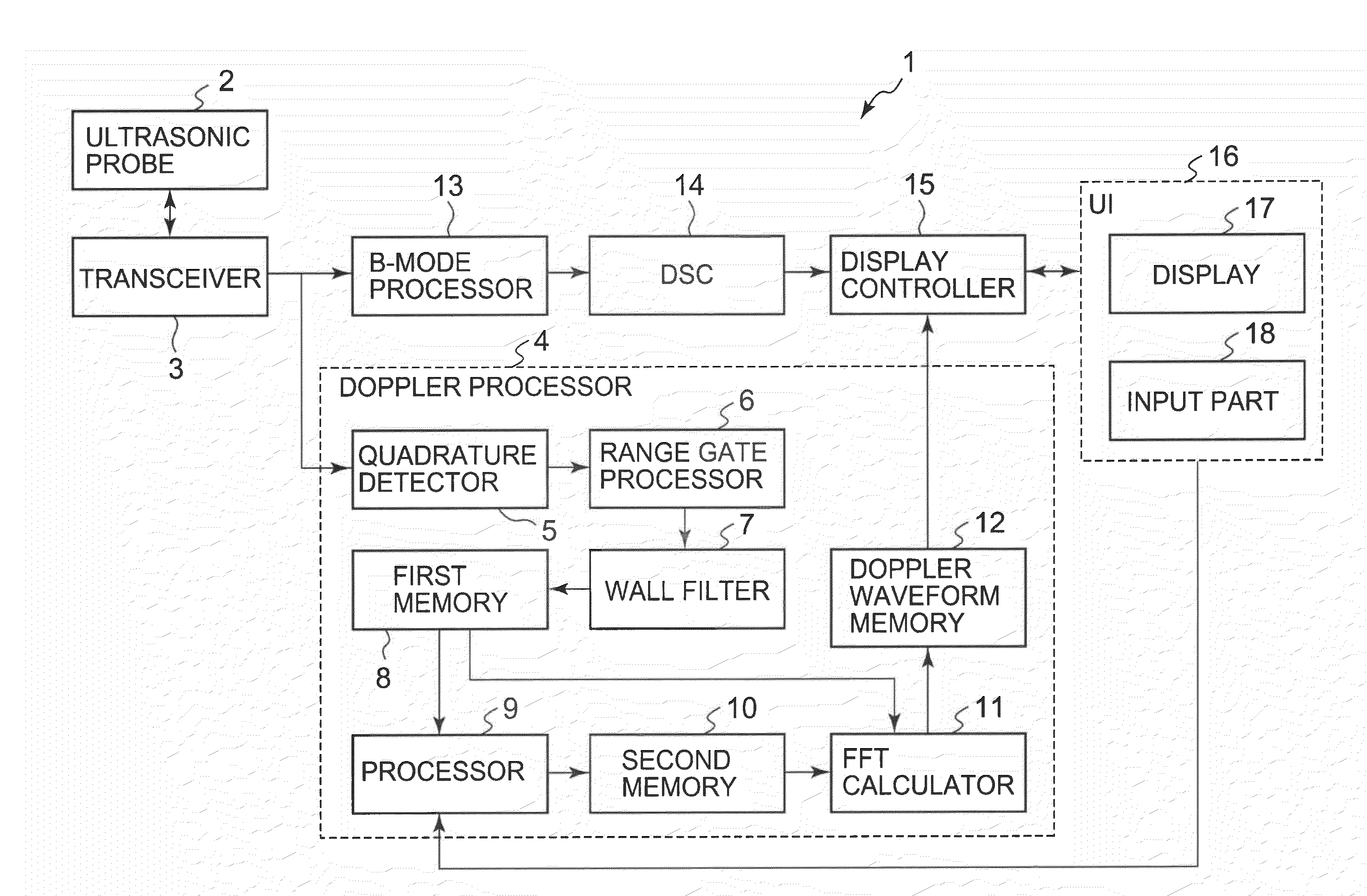
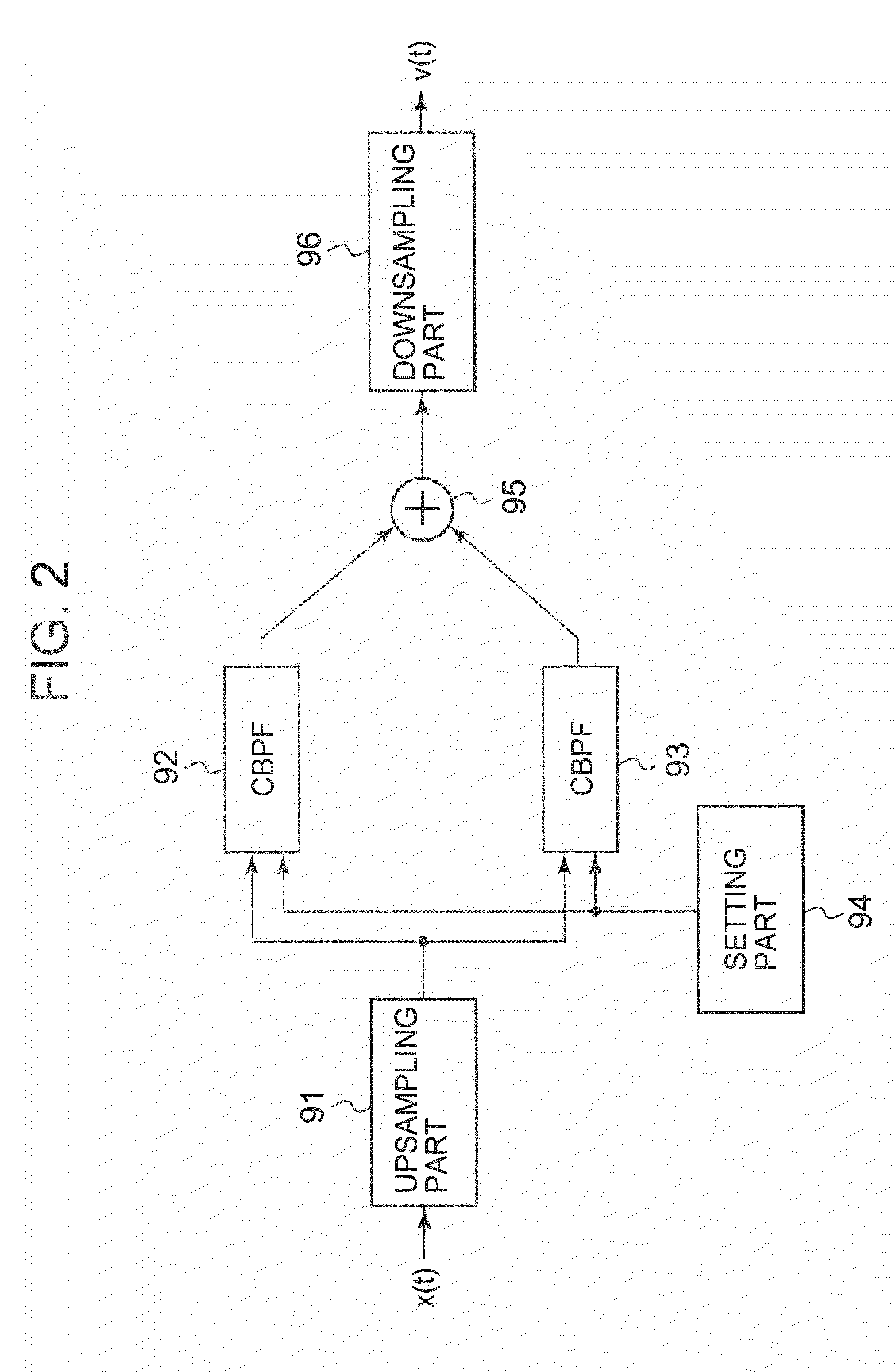
[0028]An ultrasonic imaging apparatus according to an embodiment of the present invention will be described with reference to FIG. 1 and FIG. 2. FIG. 1 is a block diagram showing the ultrasonic imaging apparatus according to the embodiment of the present invention. FIG. 2 is a block diagram showing a processor installed in the ultrasonic imaging apparatus according to the embodiment of the present invention.

[0029]An ultrasonic imaging apparatus 1 according to this embodiment comprises an ultrasonic probe 2, a transceiver 3, a Doppler processor 4, a B-mode processor 13, a DSC 14, a display controller 15, and a user interface (UI) 16. An ultrasonic image processing apparatus may be composed of the Doppler processor 4, the display controller 15 and the user interface (UI) 16.

[0030]As the ultrasonic probe 2, a ID array probe with a plurality of ultrasonic transducers aligned in a specified direction (a scanning direction) is used. Alternatively, as the ultrasonic probe 2, a 2D array pro...


PUM


Abstract

A scanner transmits and receives ultrasonic waves at a specified pulse repetition frequency (PRF). A storage stores received signals acquired through the transmission and reception. A calculator generates a Doppler spectrum image by executing frequency analysis on the received signals. A display displays the Doppler spectrum image. When a desired Doppler velocity range for the displayed Doppler spectrum image is inputted, a processor reads out the received signals from the storage, and executes a resampling process on the read-out received signals at a sampling frequency corresponding to the desired Doppler velocity range. The calculator generates a new Doppler spectrum image by executing frequency analysis corresponding to the desired Doppler velocity range on the received signals having been subjected to the resampling process by the processor. The display displays the new Doppler spectrum image.

Description

BACKGROUND OF THE INVENTION[0001]1. Field of the Invention[0002]The present invention relates to an ultrasonic imaging apparatus configured to acquire a Doppler spectrum image by transmitting and receiving ultrasonic waves to and from a subject and adjust the Doppler velocity range of the Doppler spectrum image, and also relates to a method for generating an ultrasonic image.[0003]2. Description of the Related Art[0004]An ultrasonic imaging apparatus that obtains blood-flow information of a diagnosis site by the ultrasonic Doppler method is known. The ultrasonic Doppler method is a technique of obtaining information on the blood flow in a subject based on the principles of the ultrasonic Doppler method. When ultrasonic waves are transmitted to a diagnosis site having a stream like a blood flow in a subject, the reception frequency slightly shifts from the transmission frequency by the Doppler Effect. This shift frequency (Doppler shift frequency) is proportional to a blood-flow velo...

Claims


Application Information

Patent Timeline
Patent Type & Authority Applications(United States)
IPC IPC(8): A61B8/06
CPCA61B8/06A61B8/469G01S15/584G01S7/52063G01S7/52066G01S7/52034
Inventor BABA, TATSUROKAMIYAMA, NAOHISA
Owner TOSHIBA MEDICAL SYST CORP
Why Eureka
Try Eureka