Method and apparatus for multiple-wave doppler velocity meter

a velocity meter and multiple wave technology, applied in the field of multiple wave doppler velocity meter, can solve the problems of inability to achieve satisfactory spatial resolution, inability to measure the fastest blood flow deep in the heart, and inability to meet the requirements of spatial resolution

Active Publication Date: 2012-05-24
MAYO FOUND FOR MEDICAL EDUCATION & RES
View PDF2 Cites 21 Cited by
  • Summary
  • Abstract
  • Description
  • Claims
  • Application Information

AI Technical Summary

Benefits of technology

[0017]The irradiation of the object with multiple waves includes converging or focusing the waves such that the waves overlap within their respective focal ranges. The method further includes producing interference of the first and second waves at the ROI and generating a response wave at a response frequency, the response wave being produced by a non-linear interaction of the at least two impinging waves and having several frequency components (such as a low-range frequency component, a mid-range frequency component, and a high

Problems solved by technology

One recognized limitation of this technique is that, by measuring the frequency fs, only the axial component v cos φ of the velocity can be estimated, and the knowledge of the Doppler angle φ is required to proceed with the quantitative measurement of v.
The use of Doppler technique in cardiovascular applications has an additional limitation imposed by insufficient spatial resolution of the Doppler technique.
In particular, while the measurements of the superficial blood vessels of the body can be performed with a Doppler system operating in a continuous regime, t

Method used


Image

  • Method and apparatus for multiple-wave doppler velocity meter
  • Method and apparatus for multiple-wave doppler velocity meter
  • Method and apparatus for multiple-wave doppler velocity meter

Examples


embodiment 600

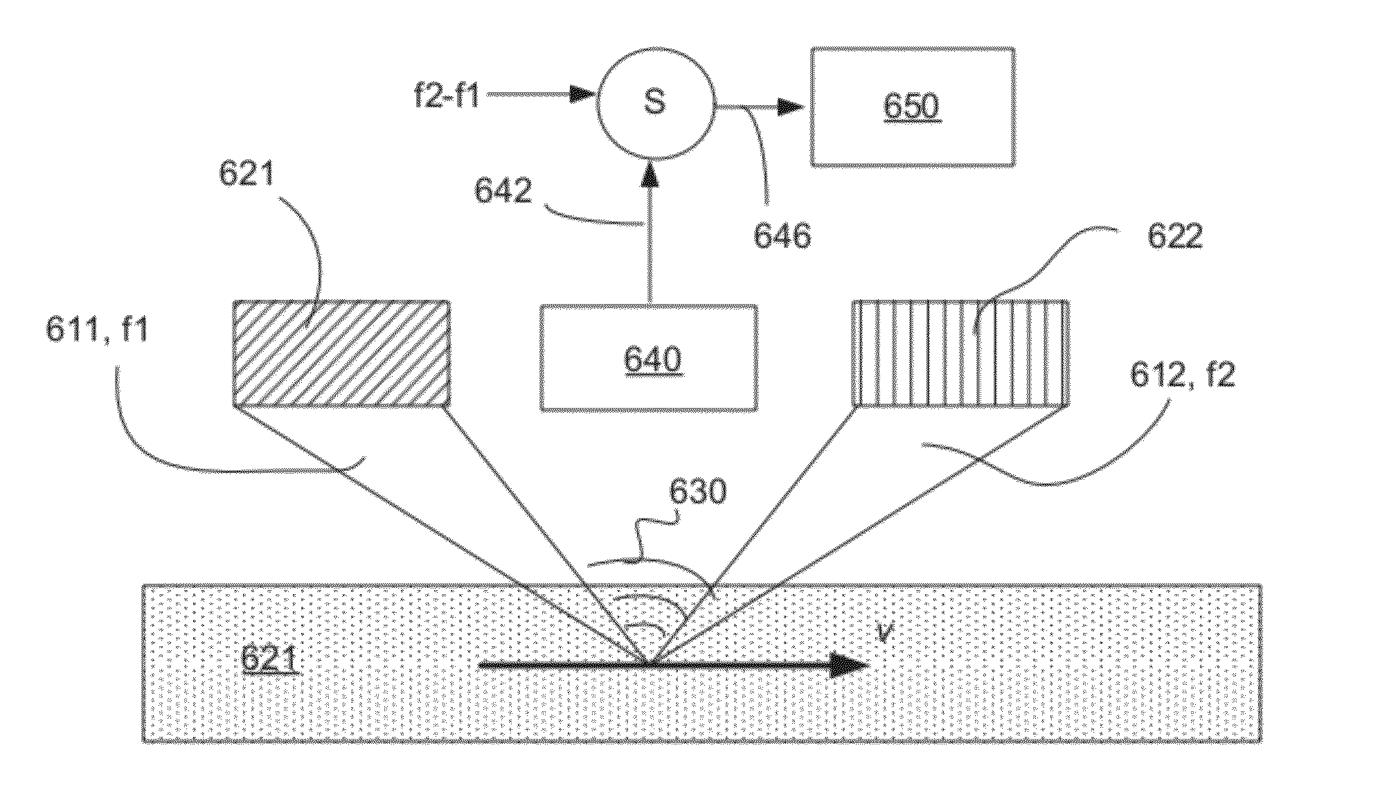
[0067]One of such modifications, an embodiment 600 that relates to the embodiment of FIG. 2, is described in reference to FIGS. 6(A, B) and in further reference to FIG. 2. As shown, two primary US waves 611, 612 (which are respectively generated by the sources 621, 622 at respectively-corresponding US frequencies f1 and f2≠f1 chosen such that the difference frequency, fΔ=f1−f2, is in the audible range) are focused at the ROI of the moving object 624. In this case, the response wave 630, generated by the moving object 621 in response to a non-linear interaction with the waves 611, 612 and received by a receiver 640, will have a frequency equal to fΔ+f′ (or fΔ−f′, depending on the direction of the flow). In a specific embodiment employing a transducer as a source of the US wave, the same transducer device may operate as a source of irradiating waves and a receiver of the response wave. FIG. 6B shows a frequency spectrum of such a response wave. The frequency component fΔis still prese...

embodiment 900

[0071]Yet another embodiment (not shown) can include - by analogy with the embodiment 900 of FIGS. 9A, 9B—three pairs of transducers respectively positioned along x, y, and z axes and operably cooperated to impinge correspondingly generated US waves onto the same ROI. Such embodiment is adapted to measure a velocity vector of the moving object in a 3D-space.

[0072]Additionally or alternatively, although some aspects of a method of the invention have been described with reference to a flowchart, those skilled in the art should readily appreciate that functions, operations, decisions, etc. of all or a portion of each block, or a combination of blocks, of the flowchart may be combined, separated into separate operations or performed in other orders. In addition, although a particular ultrasound-related embodiment of the invention and a method of detecting of the object's motion and characterizing the object's velocity have been described, the disclosed method and structure may be approp...


PUM


Abstract

A method and system for determining a velocity of a moving object such as a body or a stream. The object is irradiated in a non-collinear configuration with multiple ultrasound waves overlapping in a region-of-interest (ROI) of the object. An response wave, resulting from the non-linear interaction among the incident waves and the object, is detected and the frequency variations of the response wave are determined. Data representing a Doppler-shift of this frequency is further determined and processed to calculate the velocity of the moving object.

Description

CROSS-REFERENCE TO RELATED APPLICATIONS[0001]This application claims the benefit of and priority from a U.S. Provisional Patent Application No. 61 / 416,657 filed on Nov. 23, 2010 and titled “METHOD AND APPARATUS FOR MULTIPLE-WAVE DOPPLER VELOCITY METER.” The disclosure of the above-mentioned patent application is incorporated herein by reference in its entirety.TECHNICAL FIELD[0002]The present invention relates to systems and methods for Doppler-based tracking to measure the motion of an object. In particular, the invention relates to using of multiple wave-emitting sources and resulting wave(s) produced by the non-linear interaction of the waves emitted by such sources for the determination of the object's velocity based on the measurement of a shift in frequency of the resulting wave.BACKGROUND[0003]Doppler techniques generally rely on a direct determination of the frequency shift of the primary wave caused by reflection of the wave off of the object upon which it impinges. Dependi...

Claims


Application Information

Patent Timeline
IPC IPC(8): A61B8/06A61B8/00
CPCA61B8/06
Inventor FATEMI, MOSTAFA
Owner MAYO FOUND FOR MEDICAL EDUCATION & RES
Why Eureka
Try Eureka