

Ultrasound image capture device and ultrasound image capture method
an ultrasound image and capture device technology, applied in the field of ultrasonic imagers, can solve the problems of inability to display the flow direction, inability to determine the flow direction, and inability to ensure the reliability of the flow passage, so as to reduce the inherent uncertainty, improve the diagnostic accuracy, and reduce the effect of uncertainty
- Summary
- Abstract
- Description
- Claims
- Application Information
AI Technical Summary
Benefits of technology
Problems solved by technology
Method used
Image

Examples
first embodiment
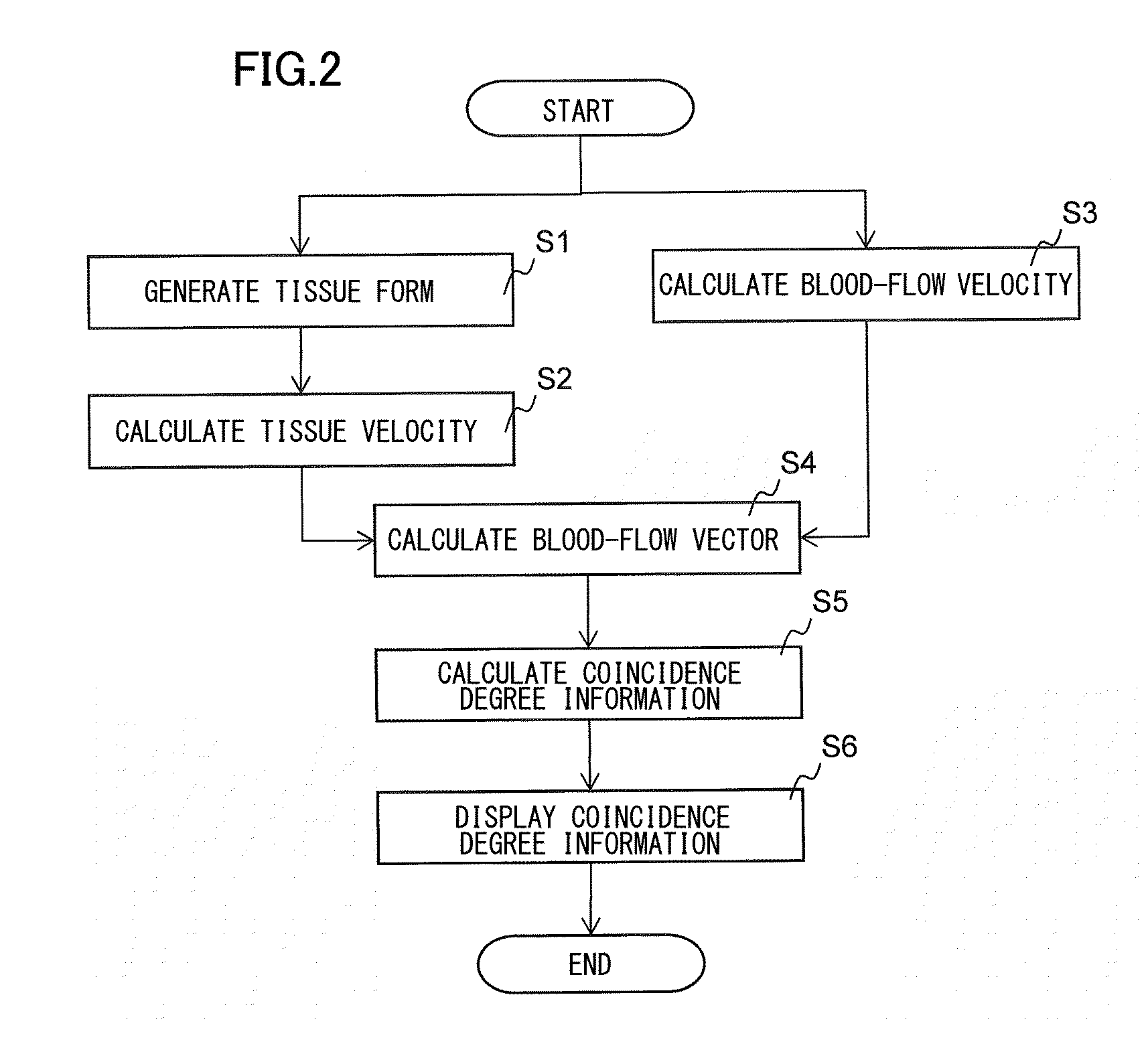
Step S1
Imaging Step
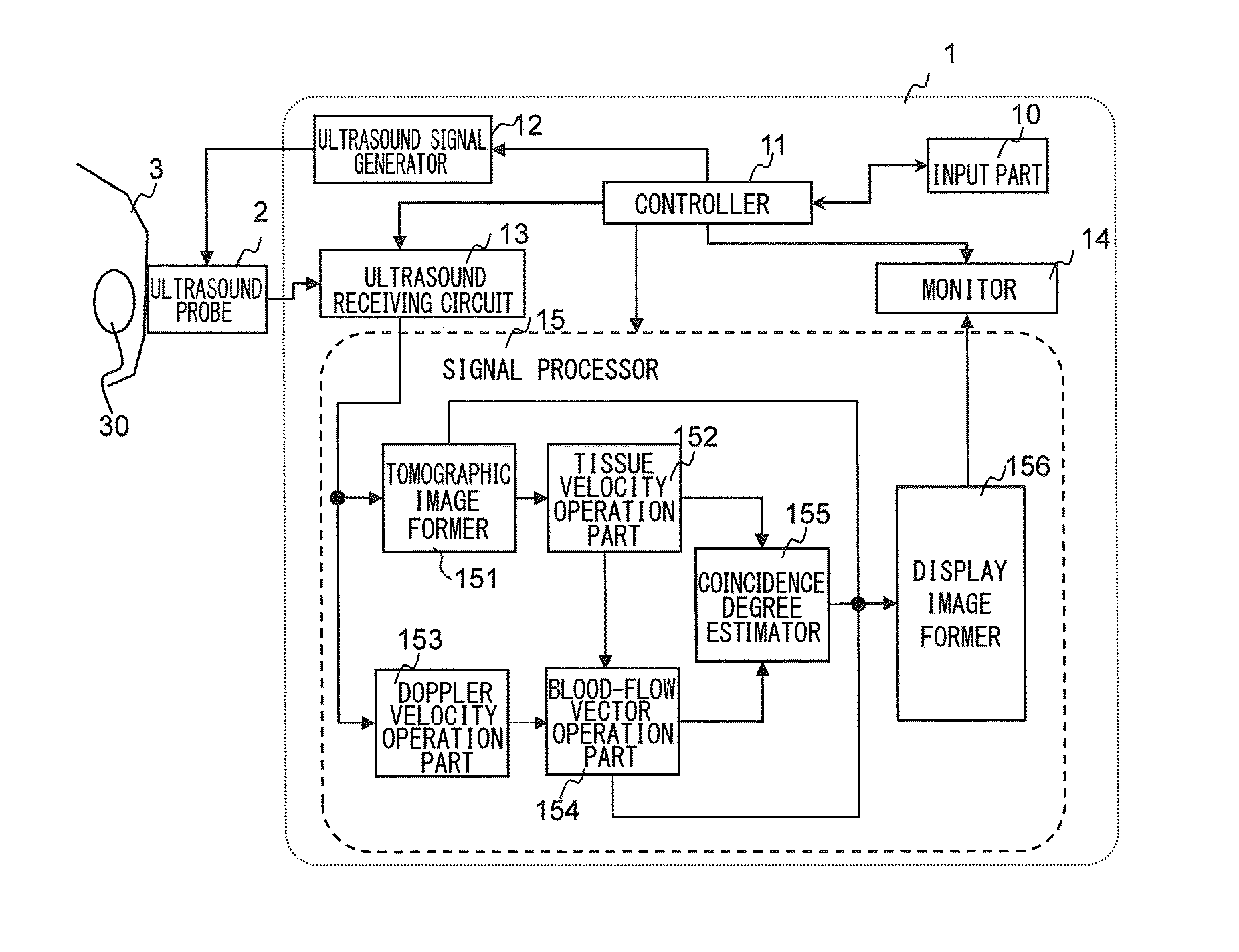
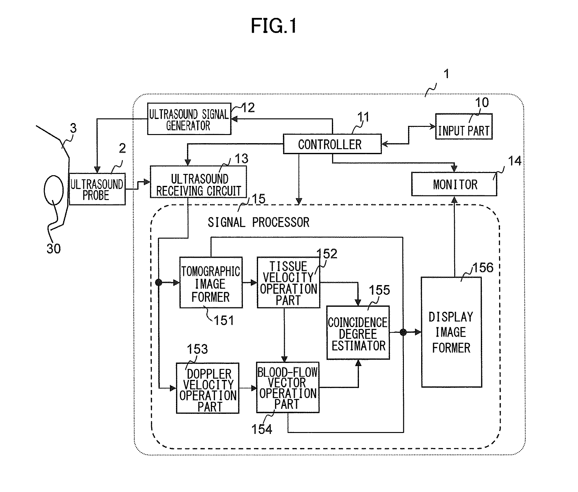
[0040]Firstly, imaging is performed so as to obtain morphological information (B-mode image) of the irradiation region. In other words, the ultrasound signal generator 12 transmits ultrasound signals at a predetermined frequency to the ultrasound probe 2, and the ultrasound receiving circuit 13 receives echo signals that are applied from the ultrasound probe 2 and reflected from the test subject 3.
[0041]The ultrasound frequency of the B-mode image falls into the range from 1 MHz to 20 MHz that enables imaging. A frame rate for taking an image of tissue that fluctuates by cardiac beats, falls into a range equal to or higher than 15 Hz, allowing the cardiac motion to be captured.
[0042]The tomographic image former 151 forms from the reflected echoes outputted from the ultrasound receiving circuit 13, for example, a B-mode image, that is, a two-dimensional ultrasound biological image of the ultrasound irradiation target by using the planar imaging method or a three-di...
second embodiment
[0085]FIG. 12 illustrates the operation of the present embodiment. In FIG. 12, the steps indicating the same operations as those of the first embodiment in FIG. 2, are labeled the same, and tedious explanation will not be made.
[0086]Also in the present embodiment as illustrated in FIG. 12, each of the steps from S1 go S6 as shown in FIG. 2 is performed, and the step S5 for calculating the coincidence degree includes the step S51 for calculating the coincidence degree and the step S52 for the statistical processing as shown in FIG. 6, in the same manner as the first embodiment or a modification example thereof. The present embodiment is characterized in that the step S5 further includes the step S7 for correcting the velocity vector, by using the coincidence degree A calculated in the step S51 and the average EA of the coincidence degrees calculated in the step S52. Correction of the velocity vector may be realized by a correction part that is added to the signal processor 15 as show...
third embodiment
[0099]The present embodiment is characterized in that it is provided with a function to store history of the coincidence degrees and the certainty calculated in the first or the second embodiment, and display a result of temporal variation. FIG. 13 illustrates a configuration example of the ultrasound diagnostic apparatus of the present embodiment. In this configuration example, the signal processor 15 is provided with a storage 157 configured to store information such as the coincidence degree, certainty, and reliability (hereinafter, referred to collectively as coincidence degree information) calculated by the velocity coincidence degree estimator 155, and a history generator 158 configured to generate history information by using the coincidence degree information acquired at different times, being stored in the storage 157.
[0100]Other configurations are the same as those of the ultrasound diagnostic apparatus as shown in FIG. 1, and tedious explanations will not be made. With re...
PUM
| Property | Measurement | Unit |
|---|---|---|
| ultrasound frequency | aaaaa | aaaaa |
| velocity | aaaaa | aaaaa |
| blood-flow velocity | aaaaa | aaaaa |
Abstract
Description
Claims
Application Information