Method for the three-dimensional viewing of tomosynthesis images in mammography

a three-dimensional viewing and tomosynthesis technology, applied in the field of three-dimensional viewing of tomosynthesis images in mammography, can solve the problems of insufficient information management, large quantity of information to be managed, and insufficient time for accessing information of clinical interest, so as to improve the accuracy of diagnosis and detection, reduce the time spent on locating radiology signs, and improve the effect of diagnostic accuracy

Active Publication Date: 2011-10-18
GENERAL ELECTRIC CO
View PDF18 Cites 13 Cited by
  • Summary
  • Abstract
  • Description
  • Claims
  • Application Information

AI Technical Summary

Benefits of technology

[0005]The invention is aimed precisely at overcoming the drawbacks of the techniques explained here above. To this end, the invention proposes a method for the viewing of the digital volume by which the practitioner can automatically detect radiology signs in series of 3D images. The time spent on locating these radiology signs is greatly reduced. Thus, the system averts a possibility of lesions being missed by the radiologist during his examination. With this method of displaying tomosynthesis images in mammography, the radiology signs are easier to identify, thus enabling a more efficient examination.
[0006]The invention proposes a novel approach to mammography that advantageously exploits the techniques of the digital processing of radiology images to improve the readability of information.
[0007]This viewing method can be used to cope with large quantities of data in developing novel strategies capable of reducing the time spent in the review of clinical data and of simplifying access to information of clinical interest.

Problems solved by technology

However, this new tomosynthesis mammography device has drawbacks.
Hence, the quantity of information to be managed is very great.
Similarly, access to information of clinical interest takes much more time because the search for this information is made sequentially, slice-by-slice, in this volume.
Moreover, depending on the space between the slices of the digital volume, the information on the presence of radiology signs is dispersed over several consecutives slices, depending on the size of the radiology signs detected, thus increasing the difficulty of access to information of clinical interest in the 3D image of the patient's breast.

Method used


Image

  • Method for the three-dimensional viewing of tomosynthesis images in mammography
  • Method for the three-dimensional viewing of tomosynthesis images in mammography
  • Method for the three-dimensional viewing of tomosynthesis images in mammography

Examples


Embodiment Construction

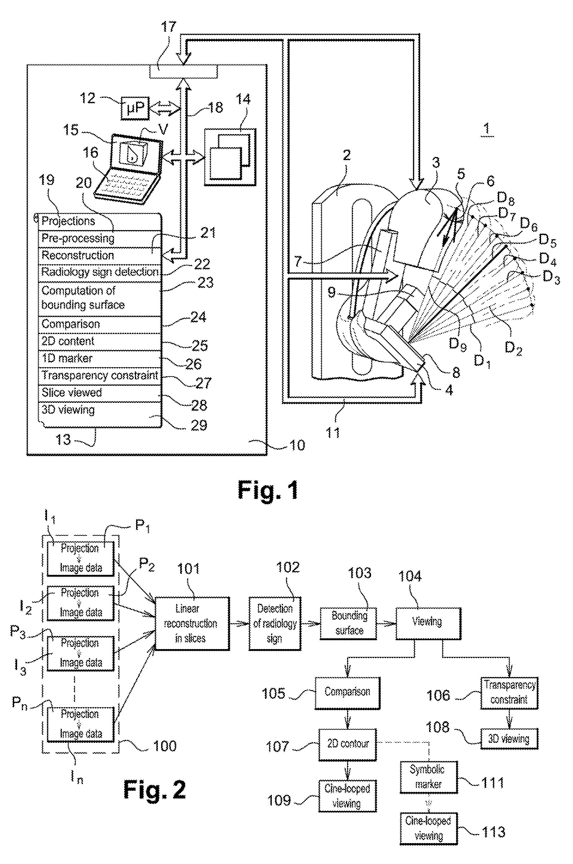
[0029]FIG. 1 shows an X-ray device, especially a mammography machine, according to the invention. This X-ray device 1 has a vertical column 2. On this vertical column, there is a hinged arm 7 bearing an X-ray emitting tube 3 and a detector 4 capable of detecting the X-rays emitted by the tube 3. This arm 7 may be oriented vertically, horizontally or obliquely. The tube 3 is provided with a focus 5 which is the X-ray emitting focus. This focus 5 emits an X-ray beam 6 along the direction of emission D.

[0030]The arm 7 is hinged on the vertical column 2 in such a way that it enables the tube 3 to be shifted along a path in the form of a circle arc while at the same time leaving the detector 4 immobile. Other arrangements are possible, enabling the tube to move in a plane or in a sphere portion. The tube 3 can then take up different positions spread in a tilt between two extreme positions. These two positions are, for example, perpendicular to the plane of the detector.

[0031]In a preferr...


PUM


Abstract

In a method for the 3D viewing of tomosynthesis images in mammography, an algorithm is proposed for the viewing of radiology signs in series of 3D data. When the digital volume is being viewed by a practitioner, the disclosed algorithm is used to provide a dynamic indication of the position of the radiology signs on the 3D image by means of markers. The use of dynamic viewing draws the practitioner's attention to the zones of clinical interest. The disclosed algorithm thus highlights all the radiology signs in the 3D image of the breast.

Description

FIELD OF THE INVENTION[0001]An object of the present invention is a method for the three-dimensional viewing of tomosynthesis images in mammography. The present invention enables a dynamic display of markers of radiology signs in the digital volume of the breast. The present invention finds particularly advantageous but non-exclusive application in medical imaging and more particularly in mammography. The present invention also relates to a station for the reviewing of medical images comprising a viewing method of this kind.DESCRIPTION OF THE PRIOR ART[0002]Mammography is now widely used for the detection of lesions and the prevention of breast cancer. There are novel mammography devices in the prior art that produce a 3D image of the patient's breast. Such devices acquire several projections of an object at different angles and then reconstruct the 3D distribution of this object using a mammography reconstruction algorithm.[0003]However, this new tomosynthesis mammography device ha...

Claims


Application Information

Patent Timeline
Patent Type & Authority Patents(United States)
IPC IPC(8): G06K9/36A61B6/03
CPCG06T7/0012G06T11/008G06T2207/30068
Inventor BERNARD, SYLVAINCORGNE, BRUNO LEIORDACHE, RAZVAN GABRIELMULLER, SERGE LOUIS WILFRID
Owner GENERAL ELECTRIC CO
Why Eureka
Try Eureka