Ultrasound image diagnosis apparatus

a technology of ultrasound image and diagnostic equipment, applied in diagnostics, medical science, applications, etc., can solve the problems of serious drawbacks to visibility and operability, difficulty in removing one probe from the connector, and difficulty in so as to improve the efficiency of ultrasound examination, facilitate exchange of ultrasound probes, and increase the visibility in and around the connector unit for coupling ultrasound probes

Active Publication Date: 2010-11-18
TOSHIBA MEDICAL SYST CORP
View PDF9 Cites 15 Cited by
  • Summary
  • Abstract
  • Description
  • Claims
  • Application Information

AI Technical Summary

Benefits of technology

[0011]According to an embodiment of the present invention, while the ultrasound examination is performed in a dimly-lit room, the visibility in and around the connector unit for coupling the ultrasound probe can be increased. Consequently, it becomes possible to easily exchange ultrasound probes during the examination. Further, a wrong selection of the ultrasound probe among a plurality of probes in a dimly-lit room can be avoided. Since the exchange of the ultrasound probes can be correctly performed in a short time, the efficiency of ultrasound examinations can be improved and the burdens on a patient and the operator can be reduced.

Problems solved by technology

However, since the examination room has a dimmed light during the ultrasound examination so as to easily observe a monitor screen of the ultrasound image diagnosis apparatus, it has been difficult to exchange the ultrasound probes.
Thus, it has been difficult for an operator to remove one probe from the connector and put another probe to the connector in a dimly-lit room.
Thus, there have been serious drawbacks of visibility and operability.
Further, since the major portions of the main body of the ultrasound image diagnosis apparatus except an operation panel are difficult to see easily, for instance, it has been difficult to confirm a printed record of the ultrasound examination in the darkened room.

Method used


Image

  • Ultrasound image diagnosis apparatus
  • Ultrasound image diagnosis apparatus
  • Ultrasound image diagnosis apparatus

Examples


Embodiment Construction

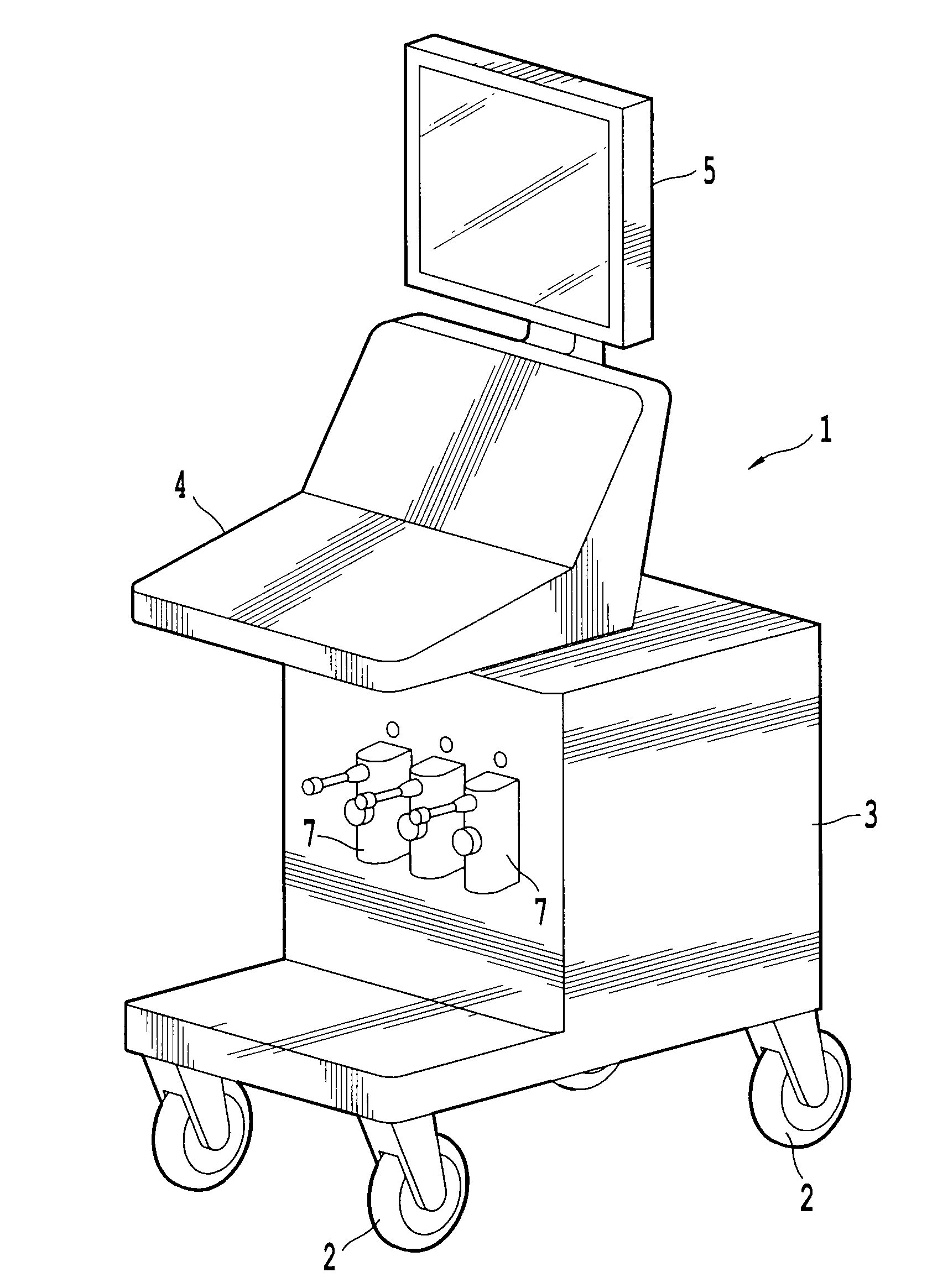
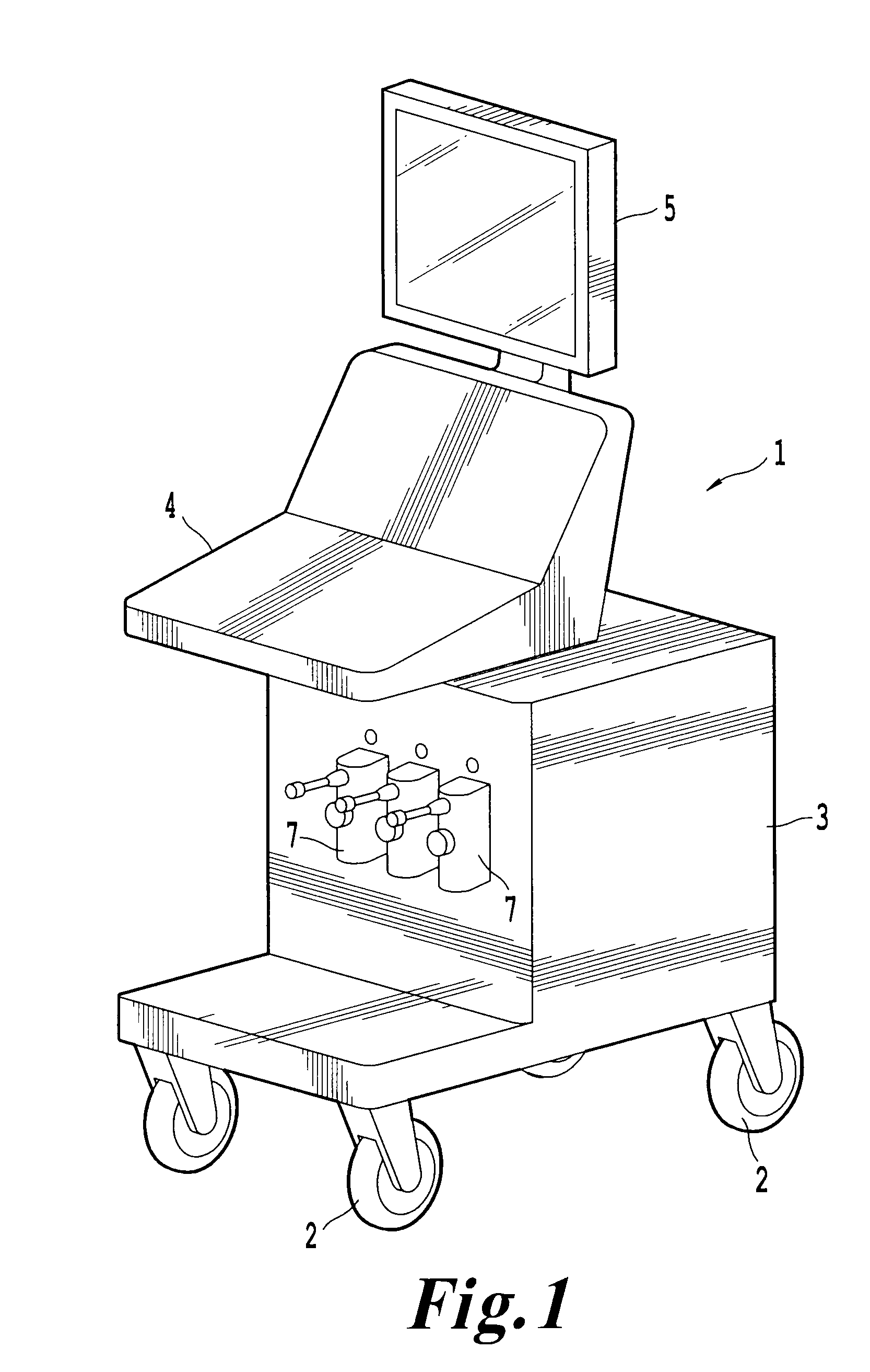
[0017]FIG. 1 illustrates an ultrasound image diagnosis apparatus 1 consistent with an embodiment of the present invention. The ultrasound image diagnosis apparatus 1 includes a main body 3 of the ultrasound image diagnosis apparatus 1, an operation panel 4, a monitor 5 for displaying ultrasound images, and an ultrasound probe 6 (not shown in FIG. 1, shown in FIG. 3) for performing transmissions and receptions of ultrasounds to and from an object (e.g. a patient). The operation panel 4 includes a touch panel and a keyboard for performing various input operations by an operator. Usually, the operation panel 4 is provided on an upper portion of the main body 3 of the ultrasound image diagnosis apparatus. To easily move the main body 3 of the ultrasound image diagnosis apparatus, it is desirable to attach casters 2 under the main body 3.

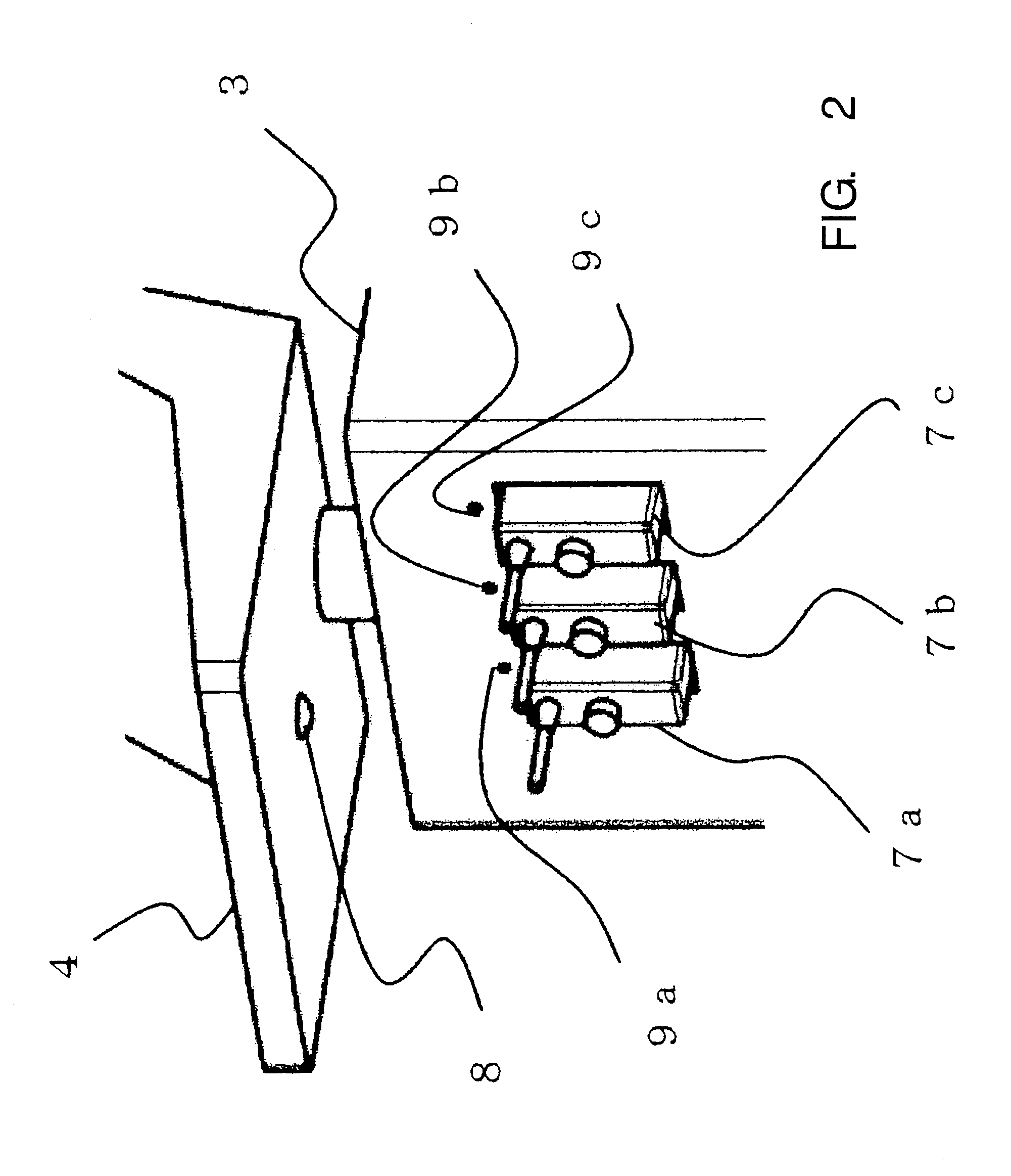
[0018]On the main body 3 of the ultrasound image diagnosis apparatus, a plurality of connectors 7a, 7b, 7c (which may simply be referred to as element 7...


PUM


Abstract

An ultrasound image diagnosis apparatus executing lighting-on and lighting-off of a lighting device by detecting an identification (ID) data of a probe or an operation on an operation panel. The ultrasound image diagnosis also includes a lighting device configured to identify a usage state or non-usage state of the ultrasound probe by a lighting color. While an ultrasound examination is performed in a dimly-lit room, a visibility of an ultrasound probe connector can be increased.

Description

CROSS-REFERENCE TO RELATED APPLICATIONS[0001]This application claims priority under 35 U.S.C. §119(a) from, and the benefit of, Japanese Patent Application No. 2009-115872, filed on May 12, 2009, the contents of which are expressly incorporated herein by reference in their entirety.BACKGROUND OF THE INVENTION[0002]A. Field of the Invention[0003]The present invention relates to an ultrasound image diagnosis apparatus, and more particularly to an ultrasound image diagnosis apparatus that can easily perform various operations, such as an exchange of an ultrasound probe, in a darkened room.[0004]B. Background of the Invention[0005]An ultrasound image diagnosis apparatus transmits ultrasound through ultrasound transducers installed in an ultrasound probe to an object, such as a patient, and receives reflected ultrasound (echo signals) due to differences of acoustic impedances of the object's organs so as to display the image of the organ on a monitor. Since an ultrasound image diagnosis ...

Claims


Application Information

Patent Timeline
Patent Type & Authority Applications(United States)
IPC IPC(8): A61B8/00
CPCA61B8/00A61B8/4438A61B8/4405
Inventor SATO, TOMOHIROHIRAKUI, KATSUYAKURAMATA, KATSUTERUONODERA, HIDEO
Owner TOSHIBA MEDICAL SYST CORP
Why Eureka
Try Eureka