Moving part coaxial cable connectors

a coaxial cable and moving part technology, applied in the field of coaxial cable connectors, can solve the problems of poor signal transport through mated connectors, ingress into mated or open connectors, and potential problems of signal emission from mated or open connectors, and achieve the effect of improving electrical continuity

Active Publication Date: 2015-09-15
HOLLAND ELECTRONICS
View PDF22 Cites 20 Cited by
  • Summary
  • Abstract
  • Description
  • Claims
  • Application Information

AI Technical Summary

Benefits of technology

[0026]The present invention includes a spring activated protruding nose for urging engaged coaxial connectors apart for improving electrical continuity in a mated connector ground path.
[0027]In an embodiment, a female F connector improves mated connector ground path continuity, the female F connector comprising: a connector body and a connector body cavity extending between opposed first and second ends of the connector body; a conductive center pin located along a centerline of the connector body; a nose having a protruding nose portion that, absent external forces, extends from an aperture in the first end of the connector body; a spring that urges the extension of the protruding nose portion; the nose having a nose cavity extending between opposed first and second ends of the nose; an end of the conductive center pin slidingly engaged with the nose cavity; and, wherein the female F connector nose is operable to urge the separation of a mated male F connector such that mating of male and female connector ground path parts is improved.
[0028]And, in some embodiments, the connector above includes a conductive pin fixing structure for preventing relative motion between the pin and the female F connector body. In an embodiment of the above connector, a cylindrical structure and a pin mouth make up all or a portion of the conductive center pin. And, in an embodiment of the above connector, the cylindrical structure is concentric about a line whose length is the shortest distance between its end points.
[0031]And, in an embodiment, a moving part coaxial cable connector comprising: a hollow connector body with first and second ends; an aperture at the connector body first end; a nose urged to project from the aperture by a spring; the spring having a design and spring constant able to project the nose when the connector is not mated; the spring having a design and spring constant able to mate connector ground path parts when the connector is mated; the nose movable in the aperture according to external forces; a conductive center pin and an adjoining pin mouth end, the pin mouth end slidably inserted in a central passageway of the nose; an electromagnetic shield incorporated in the nose; wherein when the connector is unmated, one or more connector center conductors are shielded when the nose freely projects from the aperture; and, wherein when the connector is mated, the nose is operable to urge the separation of a mated male F connector such that mating of connector ground path parts is improved.

Problems solved by technology

In the inventor's view, all of poor signal transport through mated connectors, stray signal ingress into mated or open connectors, and signal emission from mated or open connectors represent potential problems.
Stray RF signals can cause problems in CATV systems such as home CATV systems.
The open connector end exposes a normally metallically enclosed and shielded signal conductor and can be a significant source of unwanted RF ingress alone, or in the aggregate with other signal ingress locations.
Whether a CATV signal is supplied to equipment via a drop cable or via a wall mounted connector, this connection is a potential source of unwanted RF signal ingress.
Wall mounted connectors left open or coaxial cables attached to the wall mounted connector but otherwise open are points of unwanted RF signal transfers.
Similarly, drop cables such as those terminated with a male F connector become unwanted RF signal transfer points when left open.
Multiple CATV connections in a home increase the likelihood that some connections will be left open and / or unprotected, making them, for example, a potential source of unwanted RF ingress.
And, when subscribers move out of a home, CATV connections are typically left open, another situation that creates undesirable RF signal transfer points with the CATV distribution system.
But, in the usual case home CATV connections are left active and open, an undesirable but accepted practice the industry tolerates to avoid expensive service calls associated with new tenants and / or providing the CATV signal in additional rooms.
The inventor's experience shows current solutions for reducing unwanted RF ingress resulting from open connectors are not successful and / or are not widely used.
In particular, loose connectors typically have gaps in the electromagnetic containment intended to enclose signal conductors and to prevent unwanted signal ingress.
These gaps also interrupt ground path circuits.
Further, known solutions do not mitigate the problem of undesirable RF signal transfers via loose nut threads.
Known signal ingress solutions also do not generally teach urging 360 degree contact between a nut rim and mandrel flange to create an RF barrier.
Among other things, this design is not applicable to device mounted connectors and is unreliable because of uncertain contact with a center conductor.
Notably, installers hand-craft coaxial cable center conductor lengths and, where too short, these lengths fail to contact the moving center pin.
As skilled artisans will appreciate, such structures are generally ill suited to high frequency operations including frequencies over 20 MHz, a limitation far short of present day gigahertz requirements.
Such a design compromises the connector conductive center pin and compromises RF performance due to the larger size center pin required.
But, this approach also has disadvantages.
For example, there is a need for an expensive, very large outer nut to contain the new internal sleeve.
In addition, the F connector tightening tools and industry specifications generally require a standard hex nut with an 11 mm hex-hex dimension, requirements that are not possible with this inner sleeve design.
But, if the male nut is not fully tightened to the female connector, the ground connection between the cable and a connected device / cable may be faulty.
Solutions of this sort suffer a disadvantage when the cable is off-axis due to a loose nut since the expected parallel interface planes which compromises conductivity.

Method used


Image

  • Moving part coaxial cable connectors
  • Moving part coaxial cable connectors
  • Moving part coaxial cable connectors

Examples


Embodiment Construction

[0044]The disclosure provided in the following pages describes examples of some embodiments of the invention. The designs, figures, and descriptions are non-limiting examples of certain embodiments of the invention. For example, other embodiments of the disclosed device may or may not include the features described herein. Moreover, disclosed advantages and benefits may apply to only certain embodiments of the invention and should not be used to limit the disclosed inventions.

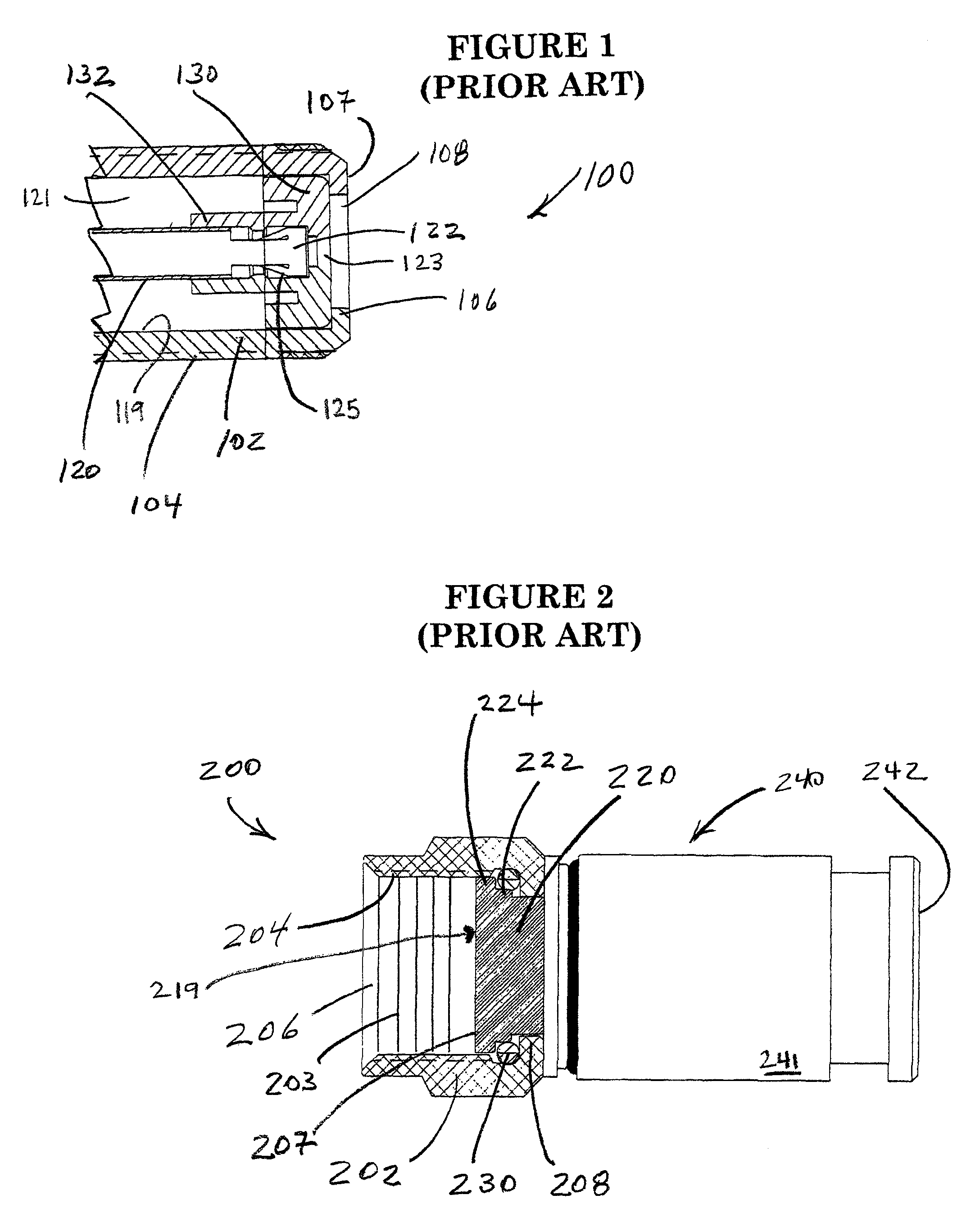
[0045]FIG. 1 shows a prior art female portion of an F coaxial cable connector (“F connector”) 100. This connector portion includes a connector body 102, a conductive pin 120 with a pin mouth 122, and a pin mouth insulator 130 for locating the pin mouth 122 about centrally in a connector body cavity 121

[0046]The body cavity 121 has a body inside wall 119 that encircles the insulator 130. In various embodiments the insulator is retained within the cavity by a female end rim 106 that presents a female end-face 107...


PUM

PropertyMeasurementUnit
frequenciesaaaaaaaaaa
external forcesaaaaaaaaaa
conductiveaaaaaaaaaa

Abstract

A female F connector incorporates a nose protruding from an end of the connector and the nose is urged to protrude by a spring.

Description

PRIORITY CLAIM AND INCORPORATION BY REFERENCE[0001]This application is a continuation-in-part of U.S. patent application Ser. No. 13 / 911,032 filed Jun. 5, 2013 and entitled MOVING PART COAXIAL CABLE CONNECTOR which claims the benefit of U.S. Provisional Patent Application No. 61 / 717,595 filed Oct. 23, 2012 and entitled MOVING PART COAXIAL CABLE CONNECTOR FOR IMPROVED SIGNAL MANAGEMENT, both of which are incorporated herein in their entireties and for all purposes.BACKGROUND OF THE INVENTION[0002]1. Field of the Invention[0003]The invention relates to articles of manufacture. In particular, a coaxial cable connector includes a moving nose urged from an opening at an end of the connector.[0004]2. Discussion of the Related Art[0005]In cable television and satellite television systems (“CATV”), signal management includes maintaining circuit continuity and reducing unwanted radio frequency (“RF”) signals exchanged at coaxial cable connectors. Among other things, signal management therefo...

Claims


Application Information

Patent Timeline
Patent Type & Authority Patents(United States)
IPC IPC(8): H01R9/05H01R43/26H01R13/17H01R13/08H01R24/52H01R13/453H01R13/6581
CPCH01R13/17H01R13/08H01R24/525H01R43/26H01R13/4538H01R13/6581Y10T29/49208
Inventor HOLLAND, MICHAEL
Owner HOLLAND ELECTRONICS
Why Eureka
Try Eureka