Piezoelectric vacuum gauge and measuring method thereof

a vacuum gauge and piezoelectric technology, applied in the field of vacuum gauges, can solve the problems of inability to measure the vacuum near the true vacuum, the structure of thin plate vacuum gauges is also complicated and expensive, and the bulkyness of spinning rotor viscosity gauges, etc., to achieve the effect of greatly simplifying production and high accuracy

Inactive Publication Date: 2015-09-22
NAT APPLIED RES LAB
View PDF18 Cites 3 Cited by
  • Summary
  • Abstract
  • Description
  • Claims
  • Application Information

AI Technical Summary

Benefits of technology

[0014]The object of the present invention is to provide a piezoelectric vacuum gauge that employs the characteristics of piezoelectric material, can simplify the complicated structure of the vacuum gauge in the prior art and can detect smaller numerical values of the pressures of vacuum.
[0031]As of now, with the advancement of technology and science, there is a need for vacuum gauges that can be used to measure the vacuum pressure during process in lab or in the development of products. In the prior art, the vacuum gauge has a complicated structure. The piezoelectric vacuum gauge of the present invention has the following advantages:
[0032](1) Structurally simple: The piezoelectric vacuum gauge of the present invention is structurally simple—with an actuating unit (made of a piezoelectric material), a sensor unit (made of a piezoelectric material) and a flexible portion. As the vibration amplitude of the flexible portion is changed due to the damping force of the remaining / ambient air, the sensor unit can immediately detect such change and convert it into an output signal.
[0033](2) High accuracy: The sensor unit, which is made of an easily available piezoelectric material, is able to detect minute changes in the remaining / ambient air. In the production of the piezoelectric vacuum gauge of the present invention, a piezoelectric material is plated onto the surface of the flexible portion; therefore, production is greatly simplified.

Problems solved by technology

However, such spinning rotor viscosity gauge is too bulky and structurally complicated.
However, such thin plate type vacuum gauge is also structurally complicated and more expensive.
However, because quarts has a low efficiency in the conversion of mechanical force to electricity, such gauge can not be used to measure lower pressures near true vacuum.

Method used


Image

  • Piezoelectric vacuum gauge and measuring method thereof
  • Piezoelectric vacuum gauge and measuring method thereof
  • Piezoelectric vacuum gauge and measuring method thereof

Examples


Embodiment Construction

[0040]The features and advantages of the present invention will be fully understood and appreciated from the following detailed description of the accompanying drawings. Although a preferred embodiment of the present invention will be described in detail hereinabove, it should be understood that the preferred embodiment is to be regarded in an illustrative manner rather than a restrictive manner.

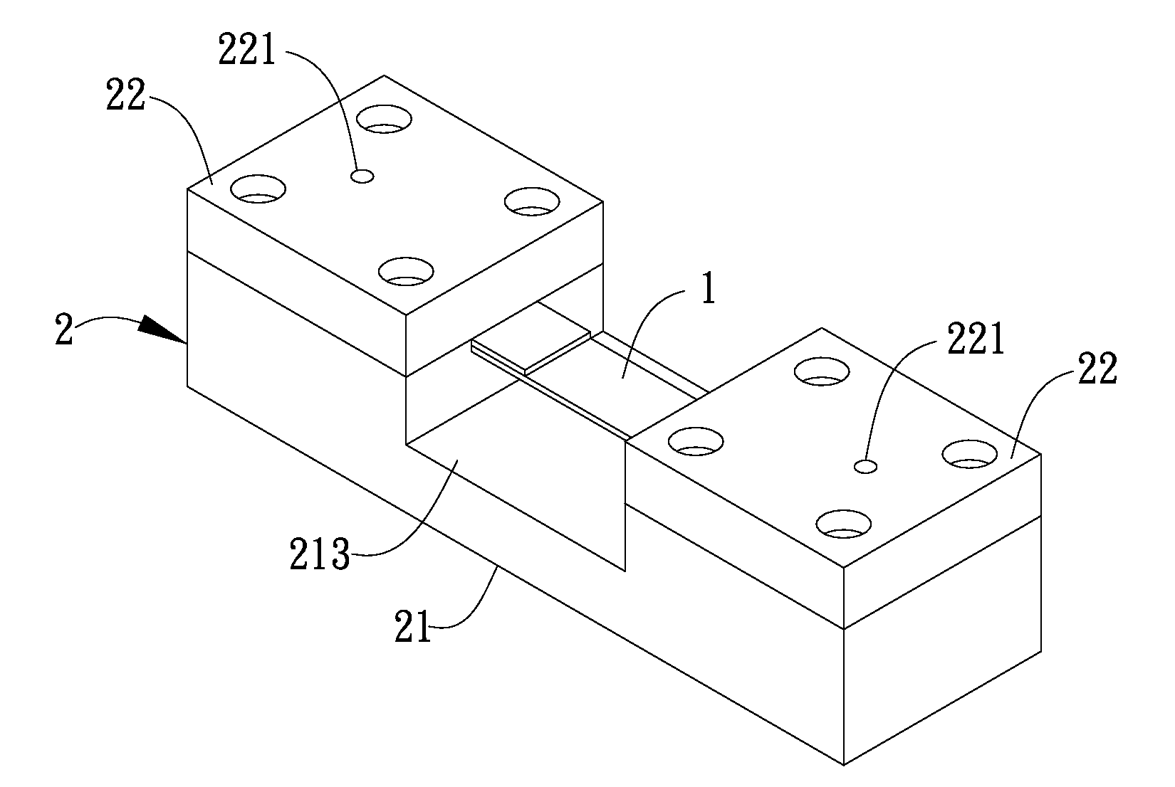
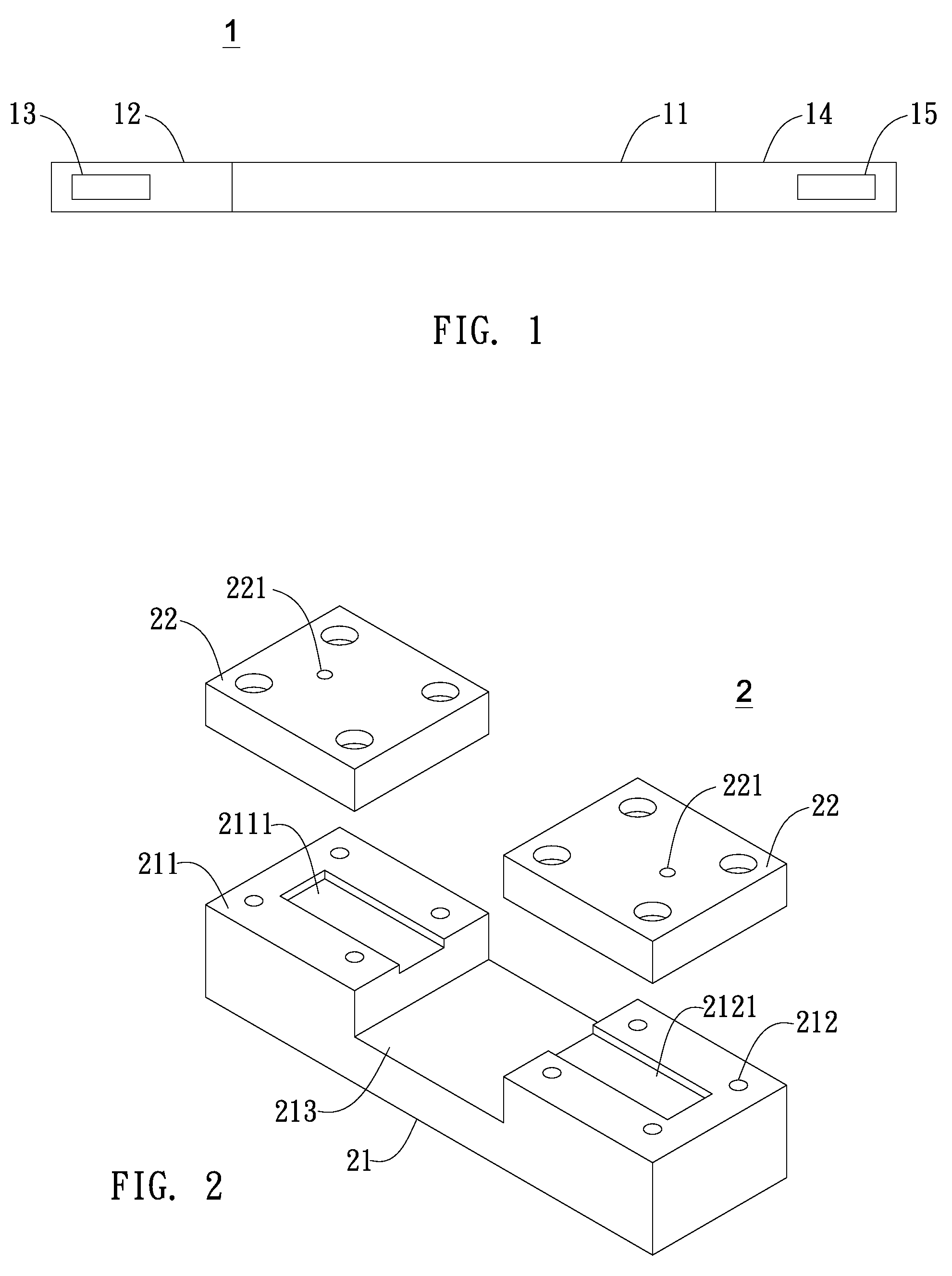
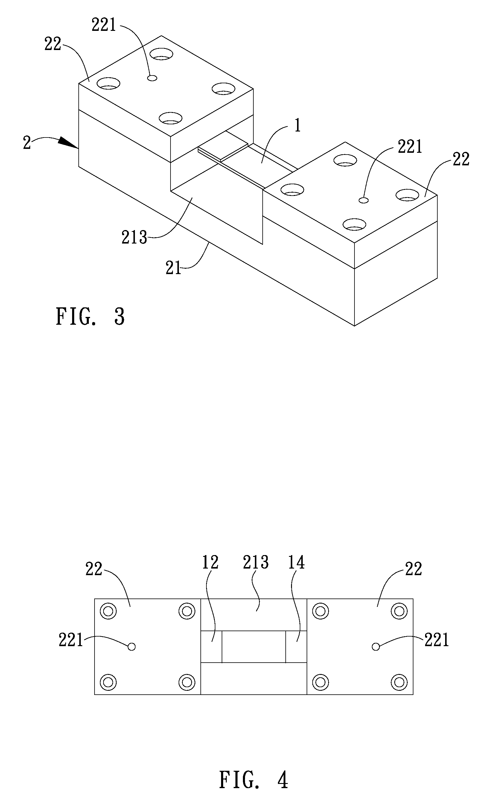
[0041]Please see FIG. 1, which illustrates the actuator of the piezoelectric vacuum gauge of the present invention. The actuator 1 comprises a flexible portion 11, an actuating unit 12, a sensor unit 14, a signal input terminal 13 and a signal output terminal 15. The flexible portion 11 is made of a metal or a plastic material and may return to its original condition after an external force exerts on it. Both the actuating unit 12 and the sensor unit 14 are made of a piezoelectric material, which may be PZT (lead zirconate titanate), AlN (aluminum nitride) or ZnO (zinc oxide). The actuating ...


PUM

PropertyMeasurementUnit
flexibleaaaaaaaaaa
vacuum pressureaaaaaaaaaa
piezoelectricaaaaaaaaaa

Abstract

A piezoelectric vacuum gauge includes an actuator with a flexible portion, an actuating unit, a sensor unit, a signal input terminal and a signal output terminal, and a fixture unit having a base portion and a cover portion. An external signal is generated by a signal generator. Receive and transmit an external signal to an actuating unit by the signal input terminal so that the actuating unit has a vibration. Prompt a flexible portion by the actuating unit to produce a first resonant motion when the actuating unit having the vibration. The first resonant motion converts into a second resonant motion because the flexible portion is subject to a damping force of ambient air. Prompt a sensor unit by the second resonant motion to cause a shape transformation of the sensor unit to generate a detecting signal. Output the detecting signal to an external instrument by a signal output terminal of sensor unit to calculate a vacuum pressure value.

Description

BACKGROUND OF THE INVENTION[0001]1. Field of the Invention[0002]The invention generally relates to a vacuum gauge. More particularly, the invention relates to a vacuum gauge that utilizes a piezoelectric material to convert a mechanical force to electrical charges according to the direct piezoelectric effect.[0003]2. Description of the Prior Art[0004]The conventional spinning rotor viscosity gauge comprises a sensor, two vertical stability control circular coils, a steel pipe and a steel ball. The steel ball is placed inside the steel pipe and one end of the steel pipe is sealed. The steel pipe can not be magnetized. In use, the steel ball is suspended between two permanent magnets of the sensor. The two vertical stability control circular coils are provided between the two permanent magnets to stabilize the steel ball in the vertical direction. In addition, two additional acceleration circular coils are provided to accelerate the steel ball. When the steel ball is accelerated to 40...

Claims


Application Information

Patent Timeline
Patent Type & Authority Patents(United States)
IPC IPC(8): G01L9/00
CPCG01L9/0022
Inventor WU, CHIA-CHECHEN, CHI-SHAOLIN, CHE-YUCHEN, FONG-ZHIHSIEH, FAN-CHUN
Owner NAT APPLIED RES LAB
Why Eureka
Try Eureka