
Vacuum cleaner

a vacuum cleaner and vacuum cleaner technology, applied in the field of vacuum cleaners, can solve the problems of lowering the cleaning efficiency

Active Publication Date: 2015-09-29
SAMSUNG ELECTRONICS CO LTD
View PDF9 Cites 39 Cited by
  • Summary
  • Abstract
  • Description
  • Claims
  • Application Information

AI Technical Summary

Benefits of technology

The solution allows for effective removal of dust and hair from the drum brush, maintaining cleaning efficiency by ensuring the drum brush can rotate freely while removing entangled debris, thus enhancing overall cleaning performance.

Problems solved by technology

As a result, cleaning efficiency is lowered.

Method used


Image

  • Vacuum cleaner
  • Vacuum cleaner
  • Vacuum cleaner

Examples


Embodiment Construction

[0045]Reference will now be made in detail to the embodiments, examples of which are illustrated in the accompanying drawings, wherein like reference numerals refer to like elements throughout.

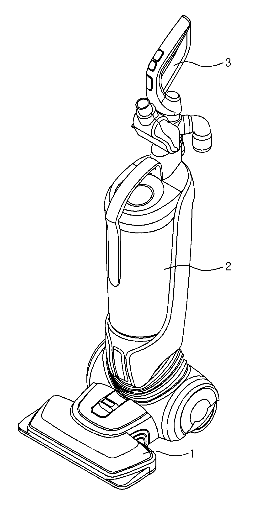
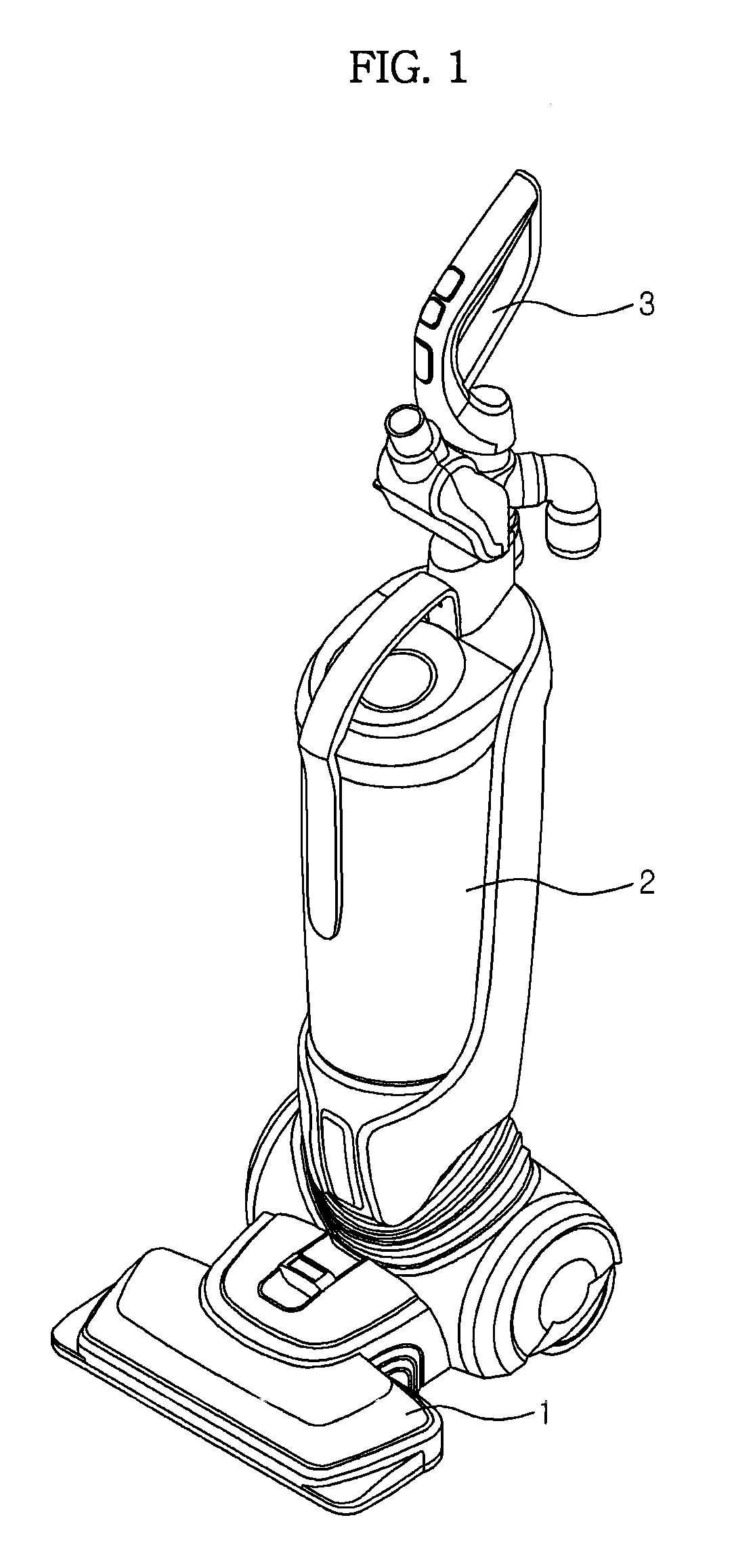
[0046]FIG. 1 is a perspective view schematically showing the external appearance of an upright cleaner according to an embodiment.

[0047]As shown in FIG. 1, the upright cleaner may include an upright main body 2, a suction body 1 mounted at the lower part of the front of the main body 2 to suction foreign matter from the floor in a room, and a handle 3 provided at the upper part of the main body 2 to allow a user to easily move the cleaner in a cleaning direction. Although not shown, a blowing device to generate suction force to suction foreign matter and a dust collection device to store the suctioned foreign matter may be mounted in the main body 2.

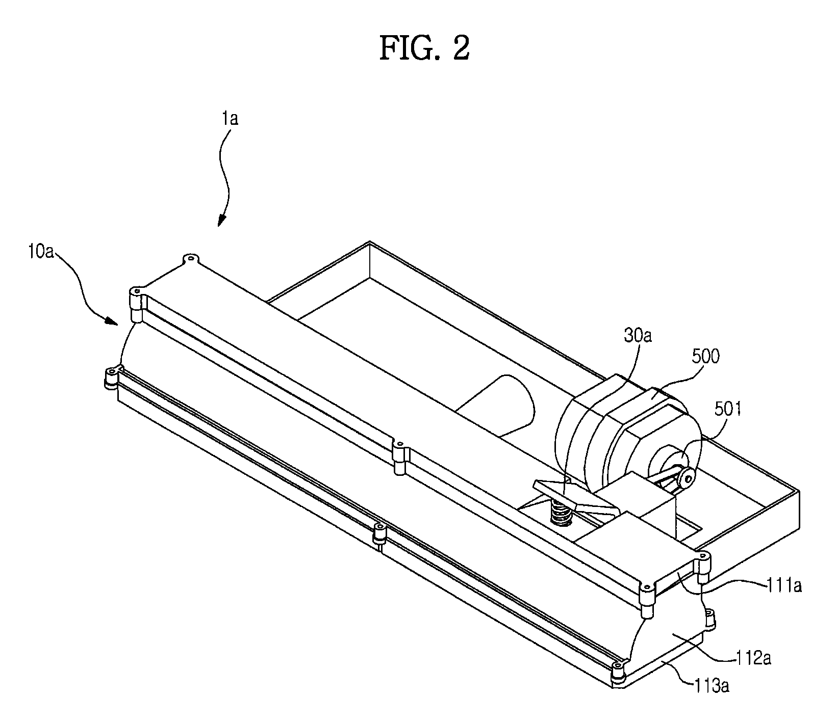
[0048]FIG. 2 is a perspective view schematically showing a suction body of the upright cleaner according to an embodiment.

[0049]FIG. 3 is an explo...


PUM


Abstract

An upright cleaner removes dust from a drum brush. The upright cleaner includes a case having a suction port, a drum brush rotatably provided in the case to sweep and guide foreign matter to the suction port, a dust removal unit provided in the case so that the dust removal unit is moved between a first position where one side of the dust removal unit contacts the drum brush and a second position where the side of the dust removal unit is separated from the drum brush, and a lever connected to the dust removal unit to actuate the dust removal unit.

Description

CROSS-REFERENCE TO RELATED APPLICATIONS[0001]This application claims the benefit of Korean Patent Application No. 10-2011-0066535, filed on Jul. 5, 2011 in the Korean Intellectual Property Office, the disclosure of which is incorporated herein by reference.BACKGROUND[0002]1. Field[0003]Embodiments relate to an upright cleaner configured to remove dust from a drum brush.[0004]2. Description of the Related Art[0005]A cleaner is an apparatus that removes foreign matter from a room to clean the room. A vacuum cleaner is generally used at home. The vacuum cleaner suctions air using suction force of a blowing device and separates foreign matter from the suctioned air using a filter to clean a room. The vacuum cleaner may be classified as a canister type vacuum cleaner or an upright vacuum cleaner.[0006]The canister type vacuum cleaner includes a main body having a blowing device and a dust collection device mounted therein, a suction body mounted separately from the main body to suction d...

Claims


Application Information

Patent Timeline
Patent Type & Authority Patents(United States)
IPC IPC(8): A47L9/20A47L9/04A47L9/16
CPCA47L9/0483A47L9/0477A47L9/20A47L9/1666A47L5/30A47L9/04A47L9/1683
Inventor YUN, MIN RO
Owner SAMSUNG ELECTRONICS CO LTD
Learn More