Gas inlet structure for a fire extinguisher

a gas inlet and fire extinguisher technology, applied in fire rescue, liquid spraying apparatus, spraying apparatus, etc., can solve the problems of inconvenient operation, decrease in pressure inside the steel bottle over time, maintenance and filling inconvenience, etc., to achieve reliable force-saving operation and improve safety

Active Publication Date: 2015-09-29
WANG CHIH CHEN
View PDF5 Cites 23 Cited by
  • Summary
  • Abstract
  • Description
  • Claims
  • Application Information

AI Technical Summary

Benefits of technology

[0005]An objective of the present invention is to provide a fire extinguisher providing improved safety and reliable force-saving operation.
[0010]In the embodiment, the gas intake control unit further includes a stop. The spring includes a bottom end abutting the bottom wall of the second coupling portion. The spring further includes a top end abutting the stop. The stop includes a through-hole through which the piercing needle extends. The through-hole of the stop has a diameter smaller than a width of the abutment portion of the piercing needle. The spring abuts the stop and the piercing needle, preventing the needle from piercing into the preserved opening of the high-pressure steel bottle when the spring is not compressed.

Problems solved by technology

However, the pressure inside the steel bottle decreases over time.
When the pressure is insufficient, gas must be filled into the steel bottle, leading to inconvenience in maintenance and filling.
However, a force must be applied to actuate the piercing needle to pierce the high-pressure steel bottle, leading to inconvenience to operation as well as unsuccessful operation if the force is too small.
Furthermore, the protective cover could be inadvertently opened by a person other than an intended user, leading to exposure of the button and subsequent pressing in error.

Method used


Image

  • Gas inlet structure for a fire extinguisher
  • Gas inlet structure for a fire extinguisher
  • Gas inlet structure for a fire extinguisher

Examples


Embodiment Construction

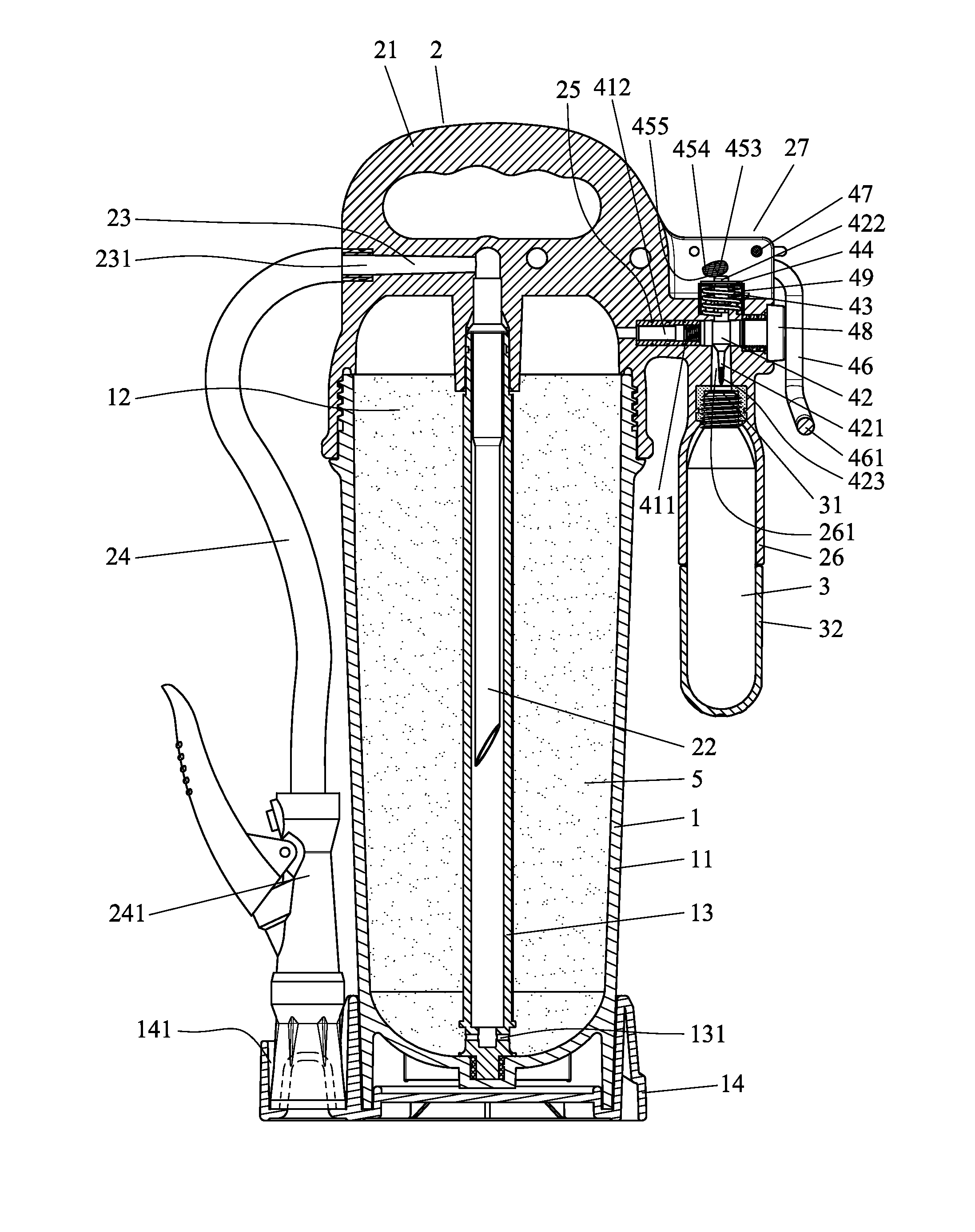
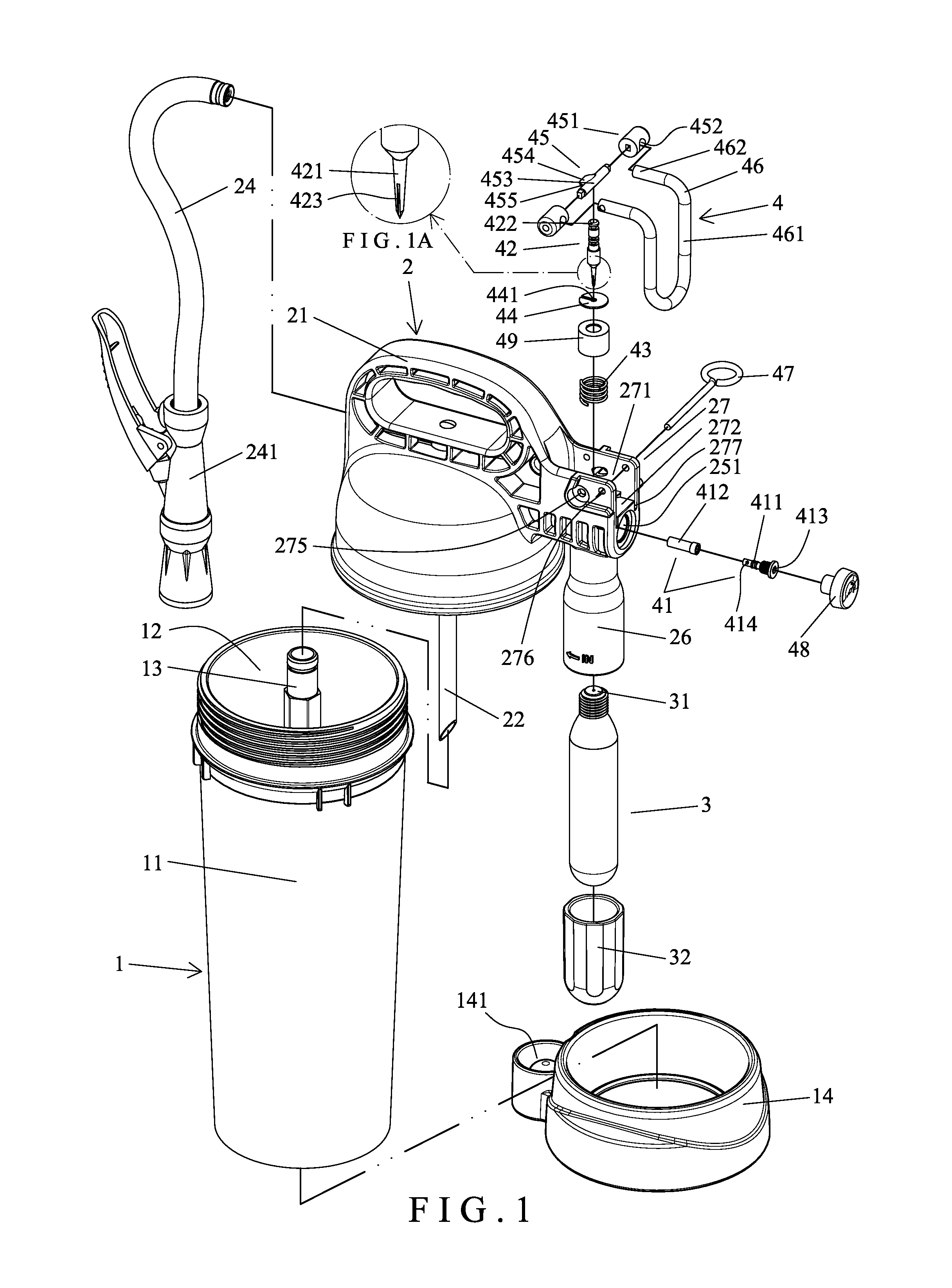
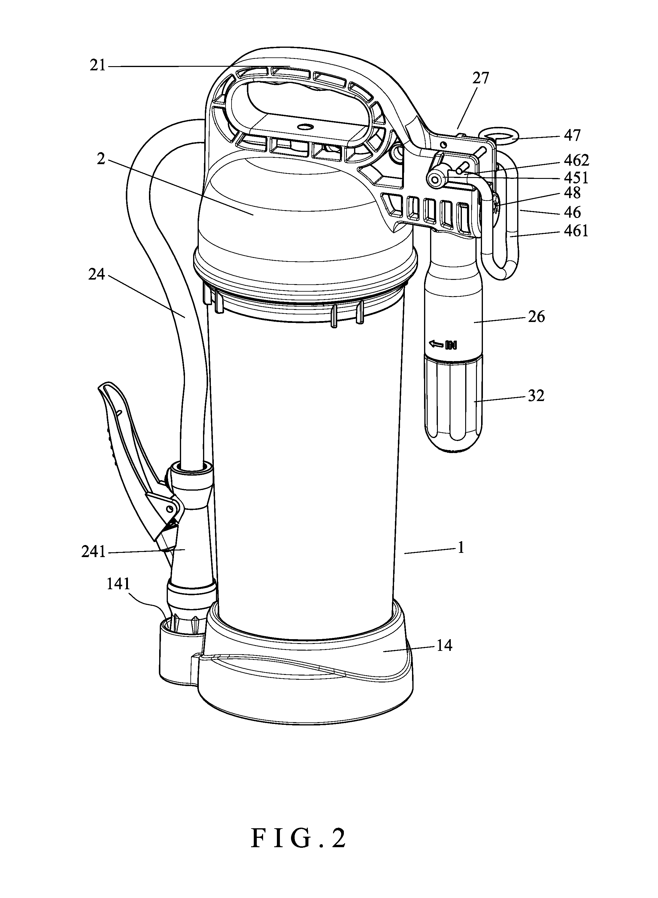
[0025]With reference to FIGS. 1-5, a fire extinguisher according to the present invention includes a body 1, an upper cover 2, a high-pressure steel bottle 3, and a gas intake control unit 4. The body 1 includes a chamber 11 for receiving fire extinguishing powders 5. The chamber 11 includes an opening 12 in an upper end of the body 1. A guiding tube 13 is mounted in a central portion of the chamber 11 and has an inlet 131 in a lower end thereof. A base 14 is mounted to a lower end of the body 1 and includes a holding groove 141.

[0026]The upper cover 2 covers the opening 12 of the body 1 and includes a handle 21 on an upper end thereof. Furthermore, the upper cover 2 includes an output passage 23 in communication with the chamber 11. The output passage 23 includes an outlet 231. An end of an output tube 24 is connected to the outlet 231, and a valve 241 is mounted in the output tube 24. When not in use, the other end of the output tube 24 is received in the holding groove 141.

[0027]...


PUM


Abstract

A fire extinguisher includes a body including a chamber receiving fire extinguishing powders. An upper cover includes a gas inlet passage and a gas intake in communication with the gas inlet passage. The upper cover further includes a through-hole aligned with the gas intake. A high-pressure steel bottle is coupled to the upper cover. The spring, when not compressed, holds the piercing needle in the gas intake and the through-hole such that the piercing needle will not pierce into a preserved opening of the high-pressure steel bottle. A pressing rod is pivotably connected to the upper cover. A switch handle is operably connected to the pressing rod. If a pin restraining movement of the switch handle is removed, when switch handle is operated to drive the pressing rod to pivot, the piercing needle is actuated by the pressing rod to pierce into the preserved opening of the high-pressure steel bottle.

Description

BACKGROUND OF THE INVENTION[0001]The present invention relates to a gas inlet structure for a fire extinguisher and, more particularly, to a gas inlet structure for a fire extinguisher providing improved safety and reliable force-saving operation.[0002]A type of fire extinguisher includes a pressurized steel bottle receiving fire extinguishing powders. In use, a valve can be pressed to output the fire extinguishing powders together with a high-pressure gas to extinguish the fire. However, the pressure inside the steel bottle decreases over time. When the pressure is insufficient, gas must be filled into the steel bottle, leading to inconvenience in maintenance and filling.[0003]To solve the above disadvantages, a high-pressure steel bottle external to the fire extinguisher is provided. The fire extinguisher includes a body receiving fire extinguisher powders. The body includes an outlet and a gas inlet. The high-pressure steel bottle is connected to the gas inlet. A piercing needle ...

Claims


Application Information

Patent Timeline
Patent Type & Authority Patents(United States)
IPC IPC(8): A62C35/58A62C13/70A62C13/00A62C13/66B05B11/06B05B7/14
CPCA62C13/70A62C13/003B05B11/06B05B11/062A62C13/66A62C13/006B05B7/1404B05B9/0833
Inventor WANG, CHIH-CHEN
Owner WANG CHIH CHEN
Why Eureka
Try Eureka