Prefabricated pillar slab system

a prefabricated and pillar technology, applied in the field of masonry structures, can solve the problems of time-consuming laying and stacking individual masonry units, prolonging the pillar construction process, and requiring mortar or expensive adhesives

Active Publication Date: 2015-09-29
RISI STONE
View PDF38 Cites 7 Cited by
  • Summary
  • Abstract
  • Description
  • Claims
  • Application Information

AI Technical Summary

Problems solved by technology

1) Laying individual masonry units such as stones or precast concrete elements in a pattern to form the basic shape desired, which is typically square or rectangular in cross-section. Each subsequent course is laid over the immediately preceding finished course, with the pattern of joints being repeated or a variation of it used, while maintaining consistent outside dimensions. It is desirable from a structural point of view to have the elements overlapping on the next subsequent course, in order to tie the individual units together to create a coherent structure. However, each individual unit within a course must be leveled independently, which is time consuming, and then fit together with adjacent elements and subsequent courses. The process of laying and stacking the individual masonry units is thus time-consuming, and generally difficult enough to require a skilled artisan such as a mason to ensure that the pillar dimensions are maintained through each course and the desired aesthetic appeal is achieved in the finished pillar.
2) Constructing the core of the pillar with concrete elements such as cinder blocks, reinforced with mortar and reinforcing steel, and then facing the resulting structural pillar core with stone and mortar, brick, stucco, or some other facing material to provide a desired aesthetic finish. However, the process of constructing the pillar core requires labourers who are skilled in block construction, mortar, and reinforcement techniques. Furthermore, the core structure must be left to cure and solidify before beginning to face the core exterior, which prolongs the pillar construction process, and the facing itself requires mortar or expensive adhesives which require additional time to cure.

Method used


Image

  • Prefabricated pillar slab system
  • Prefabricated pillar slab system
  • Prefabricated pillar slab system

Examples


Embodiment Construction

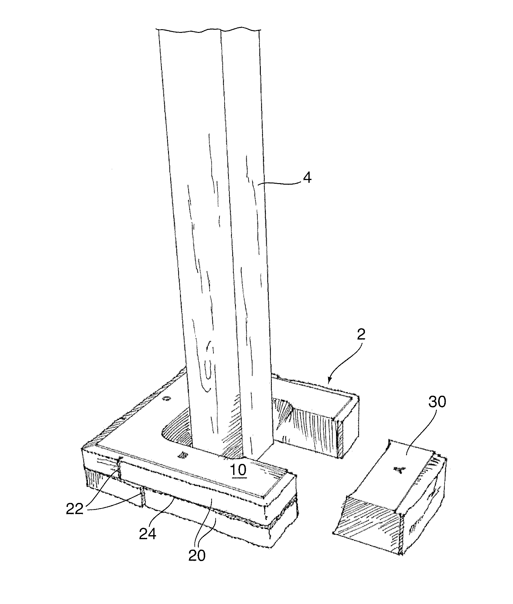
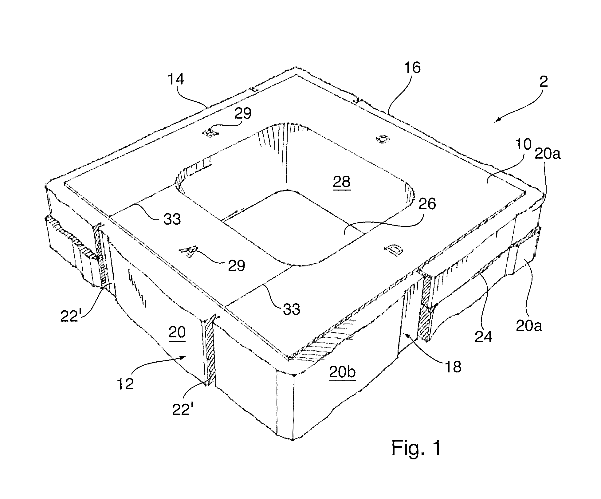
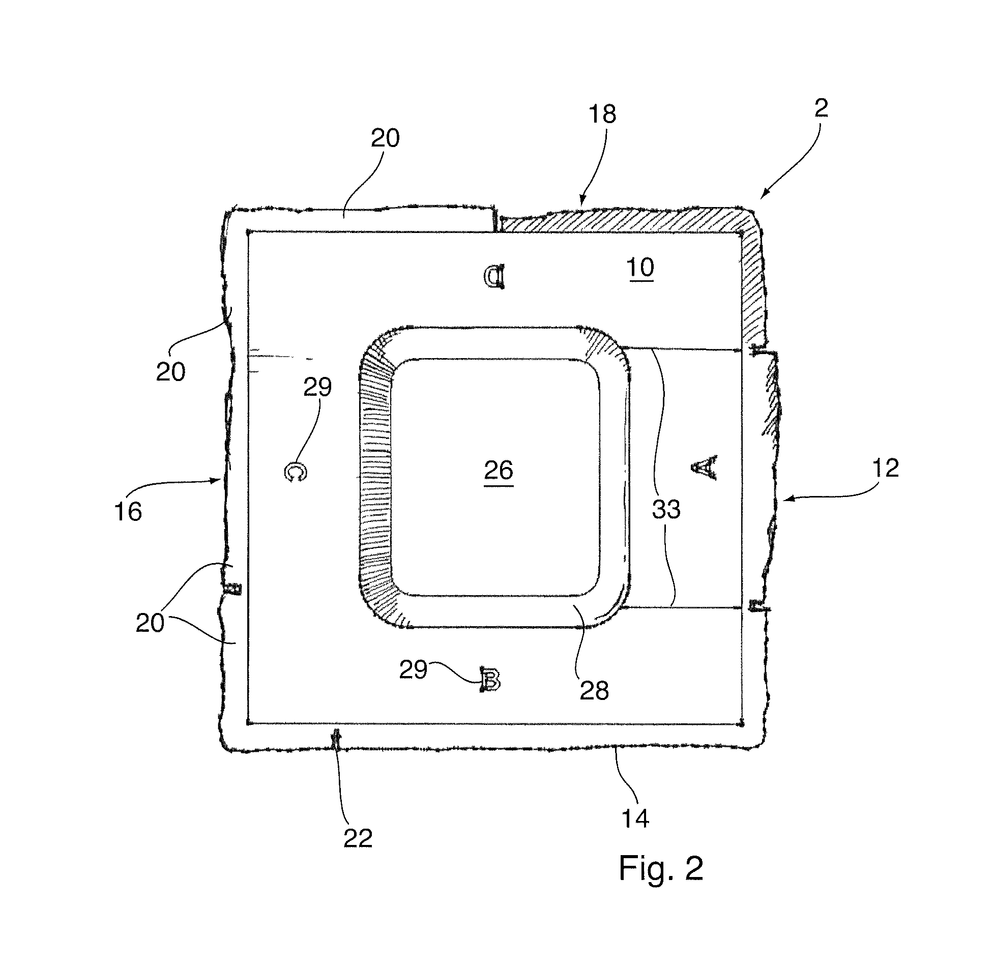
[0030]The invention eliminates one or more of the disadvantages of prior art pillar construction techniques. By providing a pillar element or “slab” as a unitary complete pillar course, the system of the invention avoids the time-consuming process of fitting together and stacking many different sizes of masonry units, significantly reduces the time required to construct a pillar, and eliminates the need for skilled or semi-skilled labour in the pillar construction process.

[0031]Using simulated joints defining simulated stone faces according to the invention, a pillar can be constructed having the appearance of multiple smaller, randomly-sized, natural stone pillar units laid in a course and overlapping each other. Moreover, according to the present invention a pillar can be constructed using a plurality of identical slabs for each course, while avoiding obvious repeating patterns in the pillar faces which would tend to detract from the ‘natural stone’ look of the exterior pillar sur...


PUM


Abstract

A pillar slab system using precast concrete pillar slabs for constructing a pillar, pergola or other stone structure comprises a body comprising at least four sides. Each exterior side surface comprises at least one simulated stone face. At least first and second side surfaces also have at least one simulated joint defining a visual separation between simulated stone faces. The simulated joints in the side surfaces are disposed at different horizontal positions, so that when one pillar slab is stacked on an identical pillar slab in a different orientation, the simulated joints in adjacent surfaces are vertically staggered relative to one another to avoid obvious repeating patterns and provide the appearance of a natural stone construction.

Description

FIELD OF THE INVENTION[0001]This invention relates to masonry structures. In particular, this invention relates to a system for constructing pillars and the like using precast concrete elements.BACKGROUND OF THE INVENTION[0002]Pillars have always been popular vertical elements in landscape design. Pillars are often made of stone or precast concrete, which as construction materials have extremely high durability and resistance to the elements. A pillar can be incorporated into another vertical element, for example forming the end of a seat wall or fence; or can stand alone, for example supporting a horizontal element such as a pediment or other roof structure, or an elevated deck. A pillar can thus serve as a structural support and / or as an aesthetic element in landscaping and building construction applications.[0003]Conventionally the two most common methods of constructing a pillar are:[0004]1) Laying individual masonry units such as stones or precast concrete elements in a pattern...

Claims


Application Information

Patent Timeline
Patent Type & Authority Patents(United States)
IPC IPC(8): E04C1/00B44F9/04E04C3/34
CPCE04C3/34B44F9/04E04C1/00E04B2/14E04B2002/0269E04C1/39E04H17/1465
Inventor MATYS, TYLER
Owner RISI STONE
Why Eureka
Try Eureka