Concealed door closer

a technology of concealed doors and closers, applied in the field of concealed doors, can solve the problems of low transmission efficiency, large structure size, low transmission efficiency, etc., and achieve the effects of preventing malicious or accidental man-made damage, small size, and high transmission efficiency

Active Publication Date: 2015-09-29
OUBAO SECURITY TECH
View PDF31 Cites 0 Cited by
  • Summary
  • Abstract
  • Description
  • Claims
  • Application Information

AI Technical Summary

Benefits of technology

[0008]In order to eliminate at least one of the above-mentioned disadvantages of the prior art, the disclosure provides a concealed door closer, which has a least one of the advantages including a smart structural design, a small size, a high transmission efficiency, including a safety protection mechanism and a long life span.

Problems solved by technology

However, such a structure has many disadvantages.
Firstly, such a structure has a large size.
Secondly, such a structure achieves a low transmission efficiency.
An externally mounted door closer needs a large rotation force, and a low transmission efficiency of the bevel, gear leads to a large drive load for the motor in the door closer, thereby greatly reducing the life span of the motor.
Thirdly, such a structure requires high precision in the mounting position.
Sometimes, the door may not be opened or closed in a normal automatic mode, or some malicious or accidental man-made damage may occur, causing the output shaft to be suddenly jammed.
In this case, the transmission mechanism and the drive motor of the door closer may be severely damaged.
After multiple damages, the operation of the door closer may be easily affected, and the door closer may be even broken.
After the measurement is done many times, the contact portion may have a positional shift, and measurement errors may be increased, thereby shifting the door closer at the door closing position and even making it impossible to close the door.

Method used


Image

  • Concealed door closer
  • Concealed door closer
  • Concealed door closer

Examples


Embodiment Construction

[0037]Hereinafter, the disclosure is described in detail with reference to the drawings:

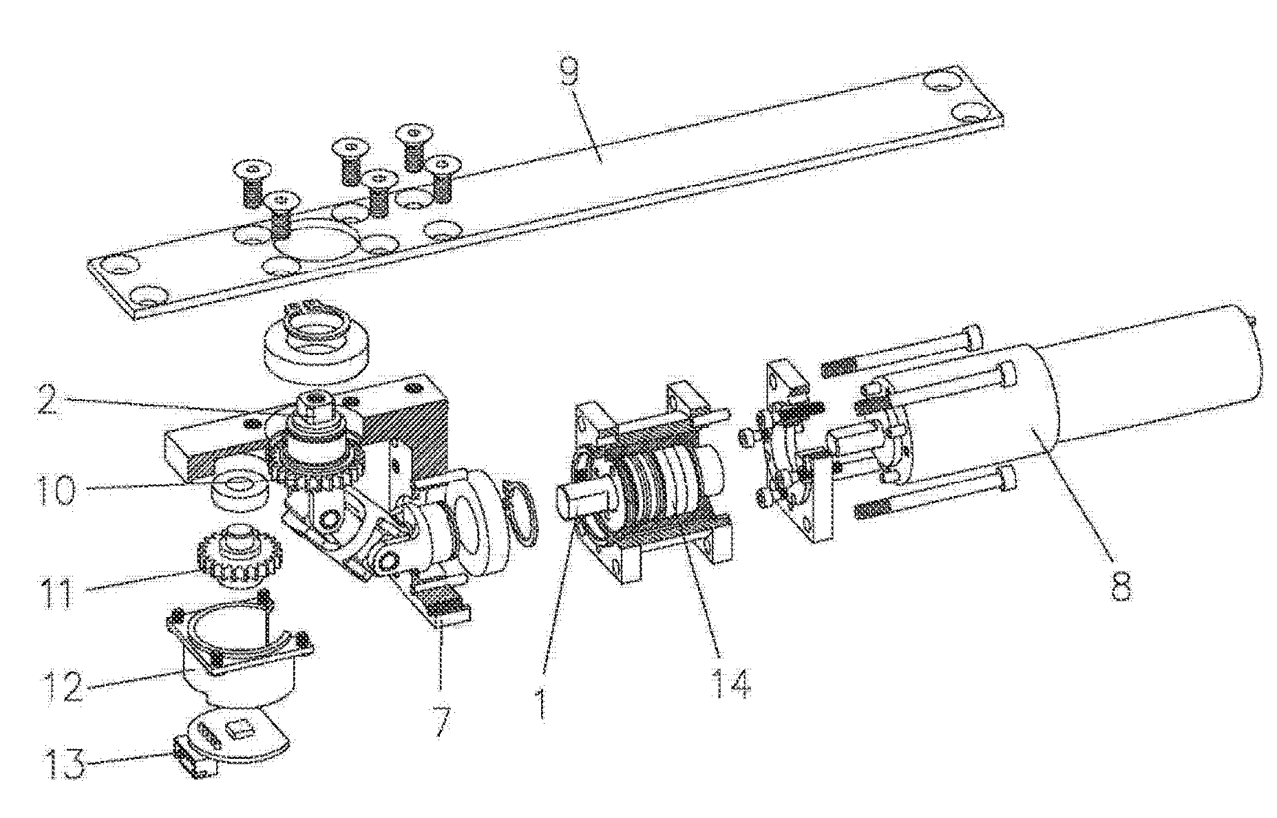
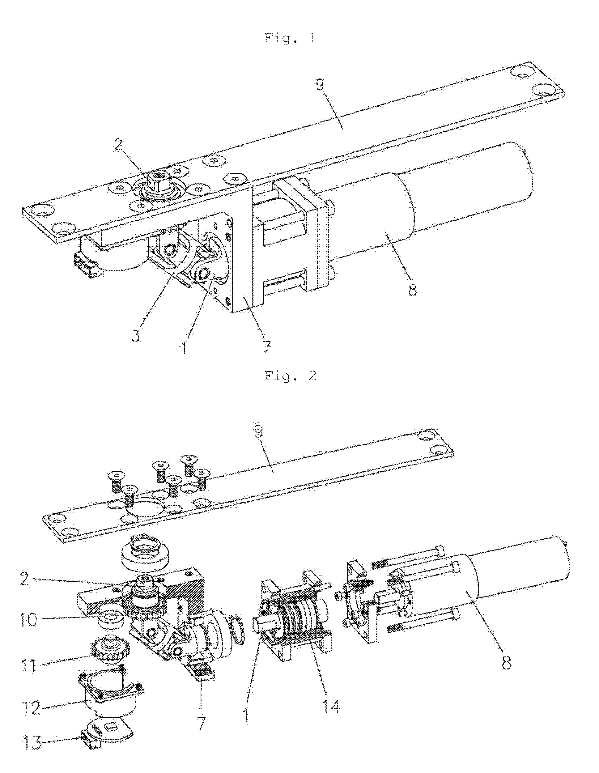
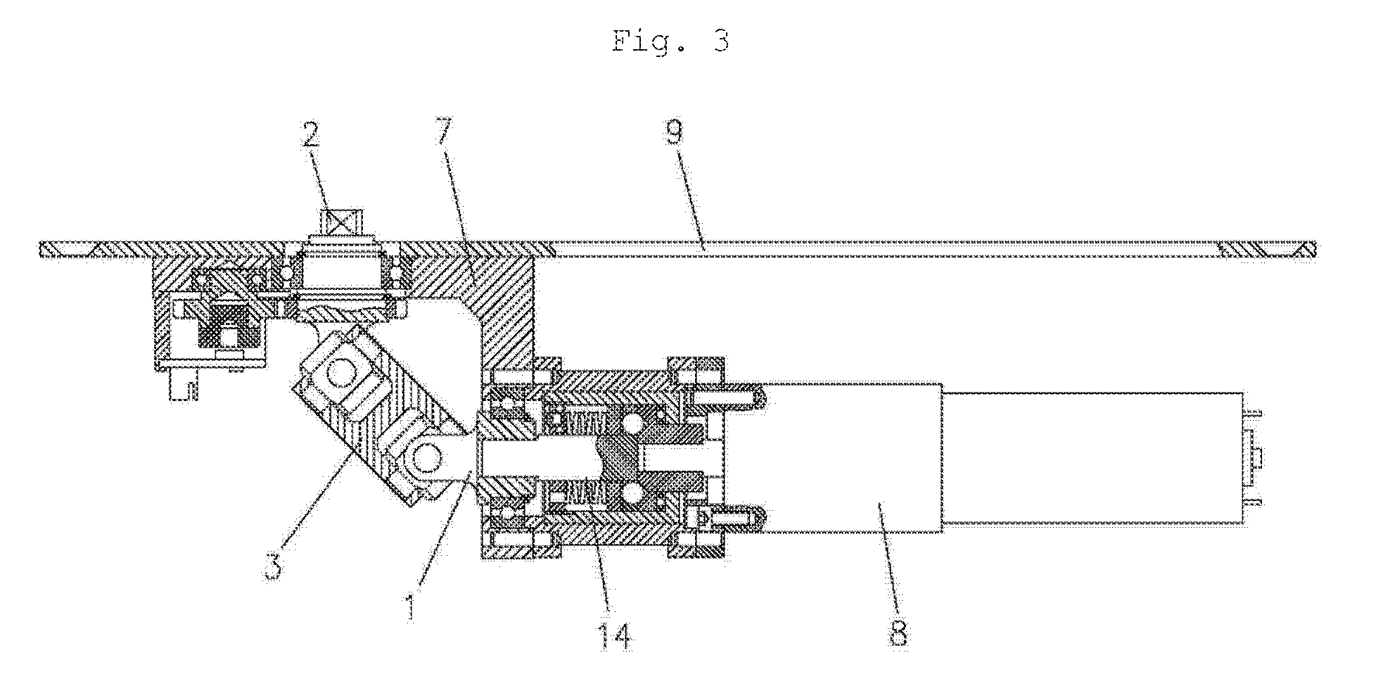
[0038]As shown in the drawings, in at least one example, a concealed door closer may include a housing 7, an input shaft 1 and an output shaft 2, the input shaft 1 being connected to a motor 8, wherein a joining member 3 is arranged between the input shaft 1 and the output shaft 2, and two ends of the joining member 3 are respectively provided with an upper connection piece 3-1 and a lower connection piece 3-2, which are connected to rollers 4 via vertical rotation shafts 5, and wherein the input shaft 1 is provided with a left connection piece 1-1 and a right connection piece 1-2, and the output shaft 2 is also provided with a left connection piece and a right connection piece, the left connection piece and the right connection piece being horizontally connected to the rollers 4 via horizontal rotation shafts 6.

[0039]In at least one example, the roller 4 has cross-like through holes 4-1, and the...


PUM


Abstract

A concealed door closer includes a housing, an input shaft and an output shaft, the input shaft being connected to a motor, wherein a joining member is arranged between the input shaft and the output shaft, and two ends of the joining member are respectively provided with an upper connection piece and a lower connection piece, which are connected to a roller via vertical rotation shaft, and wherein both the input shaft and the output shaft are provided with a left connection piece and a right connection piece, which are horizontally connected to the roller via a horizontal rotation shaft. The components in the door closer have a simple structure and may be easily processed and assembled. The size of the joint after assembly is equivalent to that of the joining member, so the overall size is small.

Description

CROSS-REFERENCE TO RELATED APPLICATIONS[0001]This application claims priority to Chinese Patent Application No. 201310121545.3, filed on Apr. 10, 2013. The entire disclosure of Chinese Patent Application No. 201310121545.3 is incorporated herein by reference.BACKGROUND[0002]1. Technical Field[0003]The present application relates to door closer, and in particular a concealed door closer.[0004]2. Background Art[0005]At present, door closers and especially some concealed door closers are more and more widely used. These concealed door closers may be hidden in doors or door frames and drive the doors to rotate via a concealed slide rail and a rock arm, thereby maintaining intrinsic aesthetic qualities of the doors. The existing door closers are usually mounted externally and employ gear mesh transmission to realize a 90-degree transmission connection between the input shaft and the output shaft. However, such a structure has many disadvantages. Firstly, such a structure has a large size...

Claims


Application Information

Patent Timeline
Patent Type & Authority Patents(United States)
IPC IPC(8): E05F15/614E05F15/63E05F15/603E05F15/611
CPCE05F15/614E05F15/603E05F15/63Y10T16/293Y10T16/299Y10T16/56Y10T16/577Y10T16/585E05Y2201/636
Inventor LI, HAOJIEFU, ZHENFENGJIANG, GUOWEIWU, ZHENBOLIU, HONGBOLAN, WEIBINZHU, CHENXIZHANG, JUNZHANG, MAOCHEN
Owner OUBAO SECURITY TECH
Why Eureka
Try Eureka