Floor panels, floor covering composed thereof, and method for manufacturing such floor panels

Active Publication Date: 2015-10-06
FLOORING IND LTD
View PDF36 Cites 15 Cited by
  • Summary
  • Abstract
  • Description
  • Claims
  • Application Information

AI Technical Summary

Benefits of technology

[0017]In a preferred embodiment of the first aspect, said adapting means, when they are applied, comprise at the respective sides horizontally active contact surfaces between both floor panels. So, for example, by means of the adapting means at least a horizontally active contact surface can be formed extending above said tongue, and/or at least a horizontally active contact surface can be formed which is situated at the underside of said tongue. This latter horizontally active contact surface then is situated preferably on said locking means. This preferred embodiment provides for that the adapting means can directly determine the mutual distance between the upper edges in the respective mutual position.
[0018]According to still another preferred embodiment of the present invention, the floor panels in said two or more mutually loc

Problems solved by technology

Such systems, however, have the disadvantage that the manner of coupling and, thus, the presence or absence of a recess or a gap between the panels, is left to the user when installing each panel.
Such system is

Method used


Image

  • Floor panels, floor covering composed thereof, and method for manufacturing such floor panels
  • Floor panels, floor covering composed thereof, and method for manufacturing such floor panels
  • Floor panels, floor covering composed thereof, and method for manufacturing such floor panels

Examples


Example

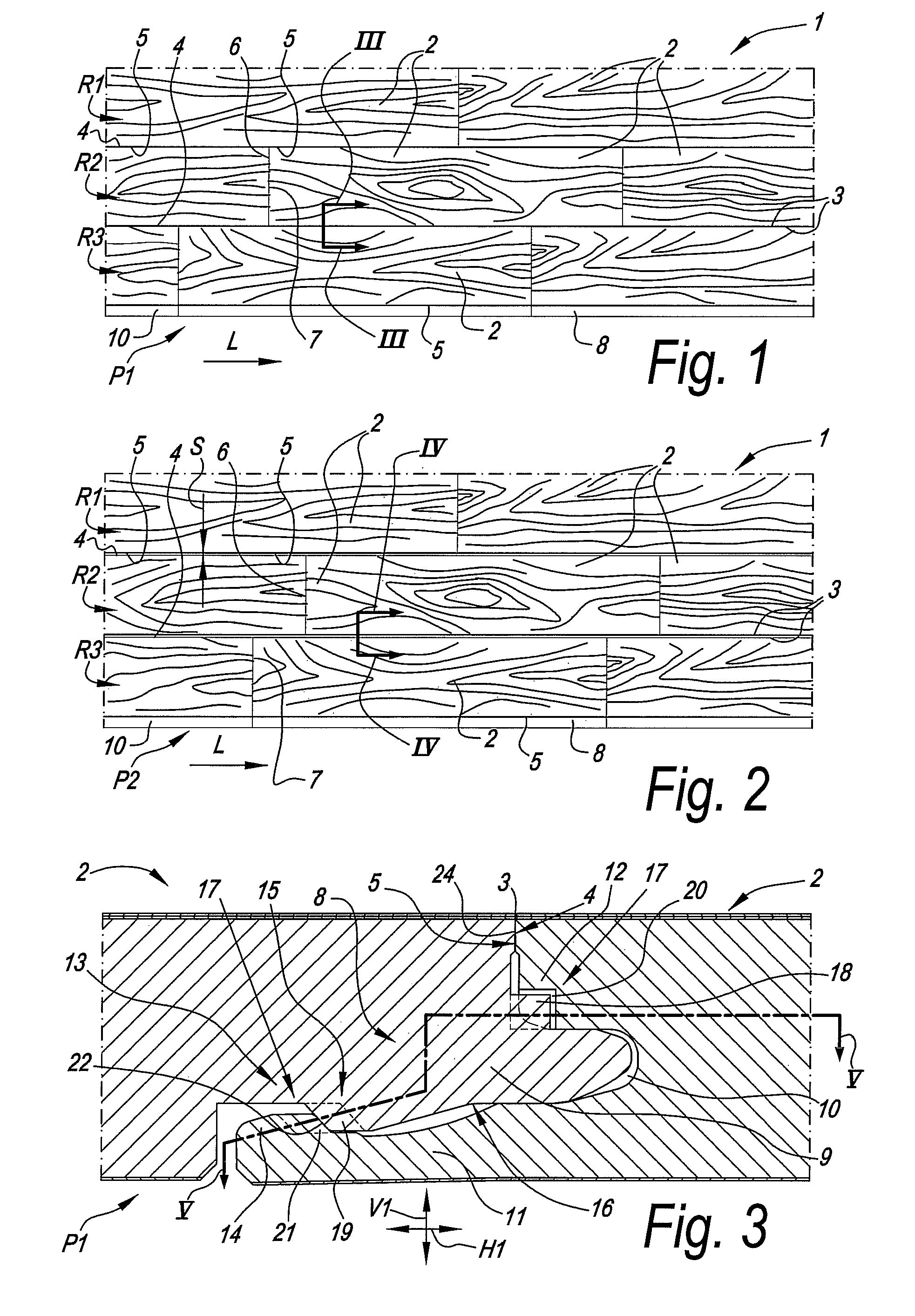
[0039]FIG. 1 represents a floor panel 1 wherein the floor panels 2 of the invention adopt mutually coupled positions P1, wherein the upper edges 3 of their adjacent coupled sides 4-5 adjoin each other, or at least fit against each other without a visible distance or gap. Here, oblong floor panels 2 are concerned, wherein the adjacent long sides 4-5 as well as the adjacent short sides 6-7 of these floor panels 2 fit against each other.

[0040]FIG. 2 represents that the floor panels 2 from FIG. 1 can also be applied for composing a floor covering 1 in which these floor panels 2 adopt other mutually coupled positions P2, wherein the upper edges 3 of their adjacent coupled long sides 4-5 do not fit against each other, but wherein the floor panels 2 at these coupled long sides 4-5 define a visible distance or gap S between their upper edges 3.

[0041]FIG. 3 represents how the floor panels 2 from FIG. 1 cooperate with each other in case they adopt a mutually coupled position P1, in which the ...


PUM

PropertyMeasurementUnit
Distanceaaaaaaaaaa
Distanceaaaaaaaaaa
Lengthaaaaaaaaaa

Abstract

Floor panel comprising coupling parts enabling two floor panels to adopt two or more different mutually locked positions (P1-P2) when coupled, wherein the two or more mutual positions (P1-P2) differ from each other in that they, at the coupled sides, define two or more different distances (S) between the upper side edges of the floor panels, and adapter elements are provided with the coupling parts, so that the use or non-use of these adapter elements enables setting the mutually locked position (P1-P2).

Description

BACKGROUND OF THE INVENTION[0001]1. Field of the Invention[0002]This invention relates to floor panels, a floor covering composed thereof, and a method for manufacturing such floor panels.[0003]2. Related Art[0004]More particularly, the invention relates to floor panels, which are intended for forming a floating floor covering and which, when being installed, can be coupled to each other at their edges by means of mechanical coupling parts, whether or not made in one piece with the floor panel, which coupling parts provide for a mutual locking of the floor panels in horizontal as well as in vertical direction, for example, as described in the international patent applications WO 94 / 26999, WO 97 / 47834, WO 01 / 98603 and WO 01 / 96688.[0005]In the meantime, it is also known to realize such floor panels in such a manner that they, when being coupled, show gaps, bevels or other chamfers at their edges. To this aim, reference is made to WO 2007 / 113676 and the already mentioned WO 01 / 96688, r...

Claims


Application Information

Patent Timeline
IPC IPC(8): E04B5/02E04F15/02E04F15/04E04B5/23E04B5/00
CPCE04F15/02005E04F15/02E04F15/04E04B5/00E04B5/02E04F2201/0107Y10T29/49629E04F15/02011
Inventor CAPPELLE, MARKTHIERS, BERNARD
Owner FLOORING IND LTD
Why Eureka
Try Eureka