
Electronic percussion instrument

a technology of electronic percussion and instruments, applied in the field of electronic percussion, can solve the problems of difficult to secure “noiselessness”, degrade sound quality, and difficult to secure adequate air ventilation in the back of the head of an electronic percussion instrument, so as to facilitate adequate air ventilation and improve workability in assembling. , the effect of improving workability

Active Publication Date: 2015-10-06
YAMAHA CORP
View PDF87 Cites 1 Cited by
  • Summary
  • Abstract
  • Description
  • Claims
  • Application Information

AI Technical Summary

Benefits of technology

The present invention helps to reduce vibration and noise in electronic percussion instruments. It does this by improving air ventilation and securing noiselessness while suppressing mechanical noise. The invention also makes it easier to assemble the head and frame of an electronic percussion instrument together due to the formation of cutouts, notches, and linear thinned portions in the head. Additionally, it allows for reliable coverage of the head without limiting air ventilation.

Problems solved by technology

However, the space in the back of die head is occupied by the cushion material which is used to maintain an impact sensor at the predetermined position, which may be an obstacle to the inlet and outlet of air; hence, it is difficult to secure adequate air ventilation in the back of the head of an electronic percussion instrument.
A large impulsive sound accompanied with art electronic musical, sound is offensive to human's ears, and therefore an impulsive sound may degrade the sound quality of an electronic percussion instrument in terms of articulation; hence, it is difficult to secure “noiselessness” in playing an electronic percussion instrument which electronically generates musical sounds.
Additionally, a large impulsive sound may degrade the durability of a head and its related parts in an electronic percussion instrument.

Method used


Image

  • Electronic percussion instrument
  • Electronic percussion instrument
  • Electronic percussion instrument

Examples


Embodiment Construction

[0048]The present invention will be described in further detail by way of examples with reference to the accompanying drawings.

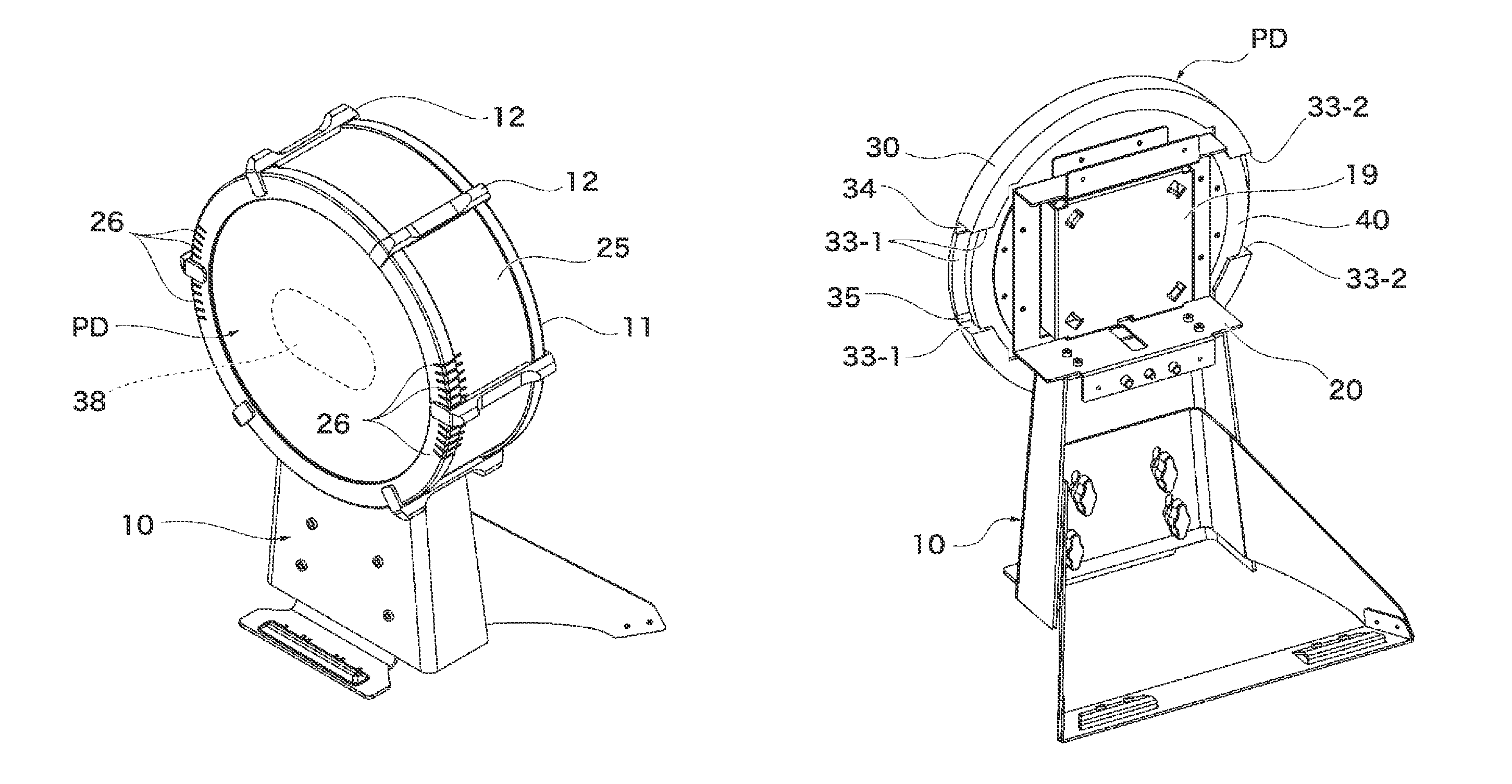
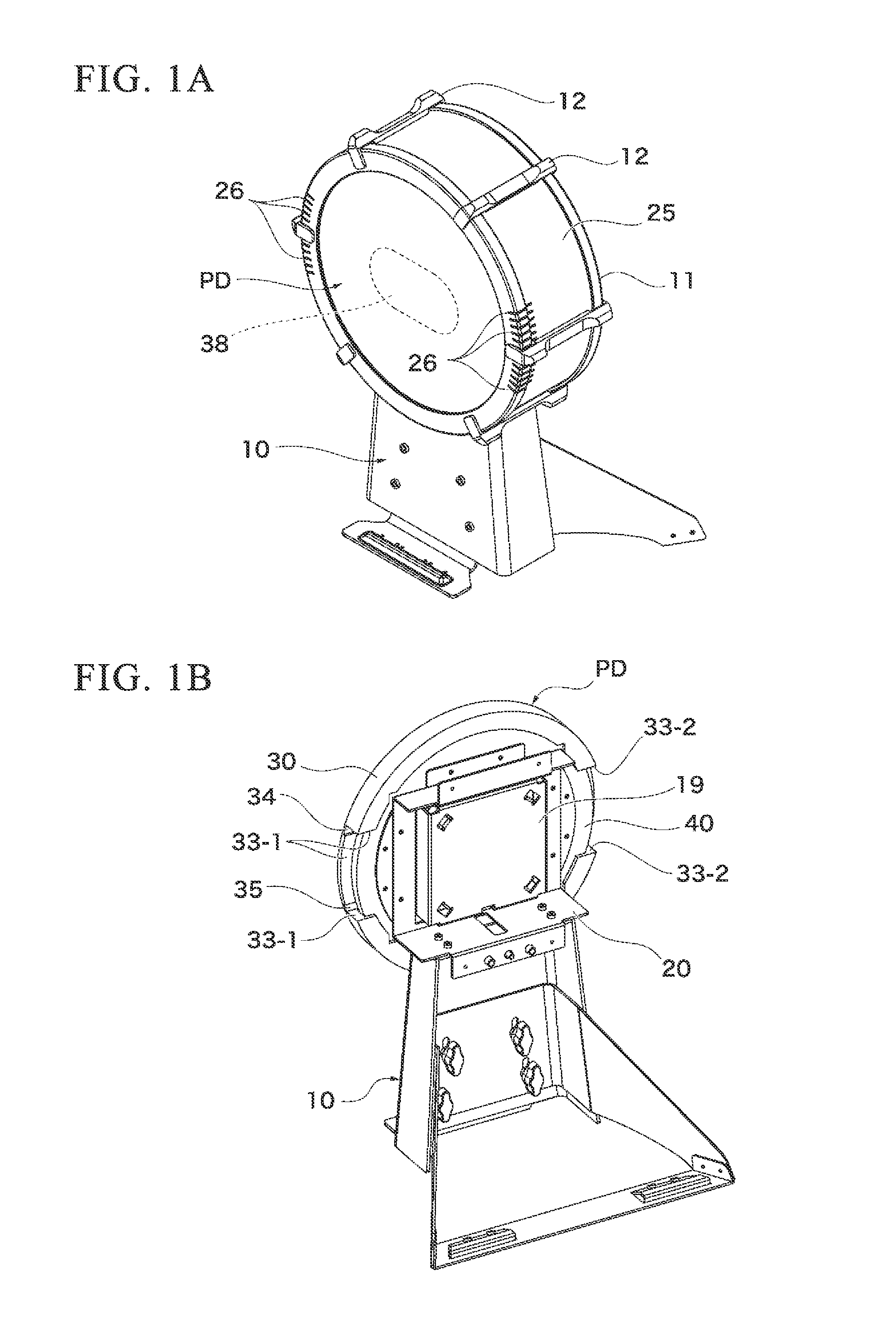
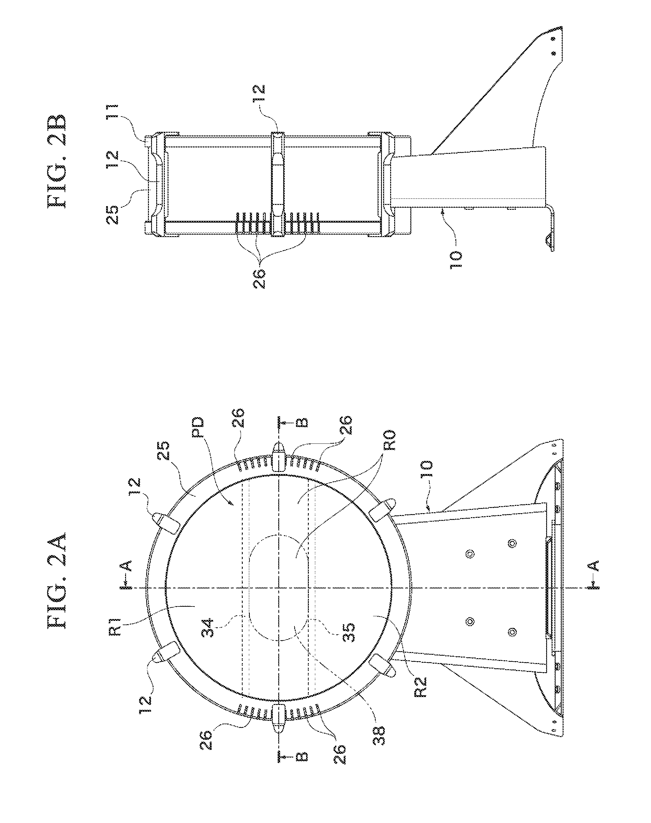
[0049]FIG. 1A is a perspective view showing the front side of an electronic percussion instrument according to the preferred embodiment of the present invention, while FIG. 1B is a perspective view showing the rear side of the electronic percussion instrument precluding covers. FIG. 2A is a front view of the electronic percussion instrument, while FIG. 2B is a side view of the electronic percussion instrument.

[0050]The electronic percussion instrument of the present embodiment serves as an electronic bass drum in which a main body serving as a kick pad is supported by a stand 10. A foot pedal device (not shown) is additionally attached to the front, side of the electronic percussion instrument in proximity to a player (e.g. a drummer) who plays the electronic percussion instrument. For convenience sake, four directions (i.e. UP, DOWN, RIGHT, LEFT) are determ...


PUM


Abstract

An electronic percussion instrument includes a head, a frame, and an impact sensor, and an air ventilation mechanism which includes a pair of cutouts which are distanced from each other and formed in the periphery of the head. The head is attached to the frame such that the periphery of the frame is externally enclosed with the periphery of the head precluding a pair of cutouts. Additionally, a pair of connecting parts with reduced thickness is linearly elongated across the back of the head in parallel. When the head is struck with a beater, a vibration is caused to occur in the head and detected by the impact sensor to produce an electric signal which is used to generate an electronic musical sound, wherein the air ventilation mechanism releases air from the back of the head so as to reliably secure noiselessness while reducing noise.

Description

BACKGROUND OF THE INVENTION[0001]1. Field of the Invention[0002]The present invention relates to an electronic percussion, instrument including an impact sensor which converts vibration of a head being struck with a beater into an electric signal so as to generate an electronic musical sound.[0003]The present application claims priority on Japanese Patent Application No. 2013-49038 and Japanese Patent Application No. 2014-47222, the entire content of which is incorporated herein by reference.[0004]2. Description of the Related Art[0005]Conventionally-known electronic percussion instruments are designed to generate an electronic musical sound based on an electric signal output from an impact sensor which detects vibration of a head being struck with a beater. Patent Literature Document 1 (PLT1) discloses an electronic percussion instrument serving as an electronic bass drum with a circular head, made of an elastic material whose periphery is engaged with a frame. An impact sensor is ...

Claims


Application Information

Patent Timeline
Patent Type & Authority Patents(United States)
IPC IPC(8): G10H1/32G10D13/02G10H7/00G10H3/14
CPCG10H1/32G10D13/024G10H3/143G10H7/00G10H2230/251G10H3/146G10H2220/525G10H2230/291G10D13/26G10D13/02
Inventor KANAYAMA, EMISATO, MASAO
Owner YAMAHA CORP
Learn More