Uplink noise minimization

a signal repeating system and noise minimization technology, applied in power management, electrical equipment, radio transmission, etc., can solve the problems of desensitization of base stations, reducing the range of mobiles or the maximum distance, and adding the noise floors of each of the remote units

Active Publication Date: 2015-10-06
COMMSCOPE TECH LLC
View PDF19 Cites 9 Cited by
  • Summary
  • Abstract
  • Description
  • Claims
  • Application Information

AI Technical Summary

Problems solved by technology

Many challenges exist with contemporary distributed antenna systems, one of which is maintaining a suitable noise floor in the system.
Summing of the uplink signals from the various multiple remote units cumulatively adds the noise floors of each of the remote units.
Since mobile units have a limited amount of transmit power that they can generate, this required increase in transmit power for the repeating system ultimately decreases range of the mobiles or the maximum distance from the remote unit of the distributed antenna system that the mobile unit can effectively communicate.
An additional challenge caused by the large noise floor rise is base station desensitization.
When this occurs, the base station will be desensitized, potentially resulting in a shrinking coverage area for the base station.
In this situation, adding the distributed antenna system noise to the base station noise will result in only about a 0.4 dB rise in the overall floor noise at the base station receiver.
Therefore, while muting one or more remotes do assist in reducing base station desensitization slightly, it does not allow the mobile unit to significantly decrease its transmit power.
Therefore, such a feature does not address the problems noted above or significantly increase the range of a distributed antenna system remote unit.

Method used


Image

  • Uplink noise minimization
  • Uplink noise minimization
  • Uplink noise minimization

Examples


Embodiment Construction

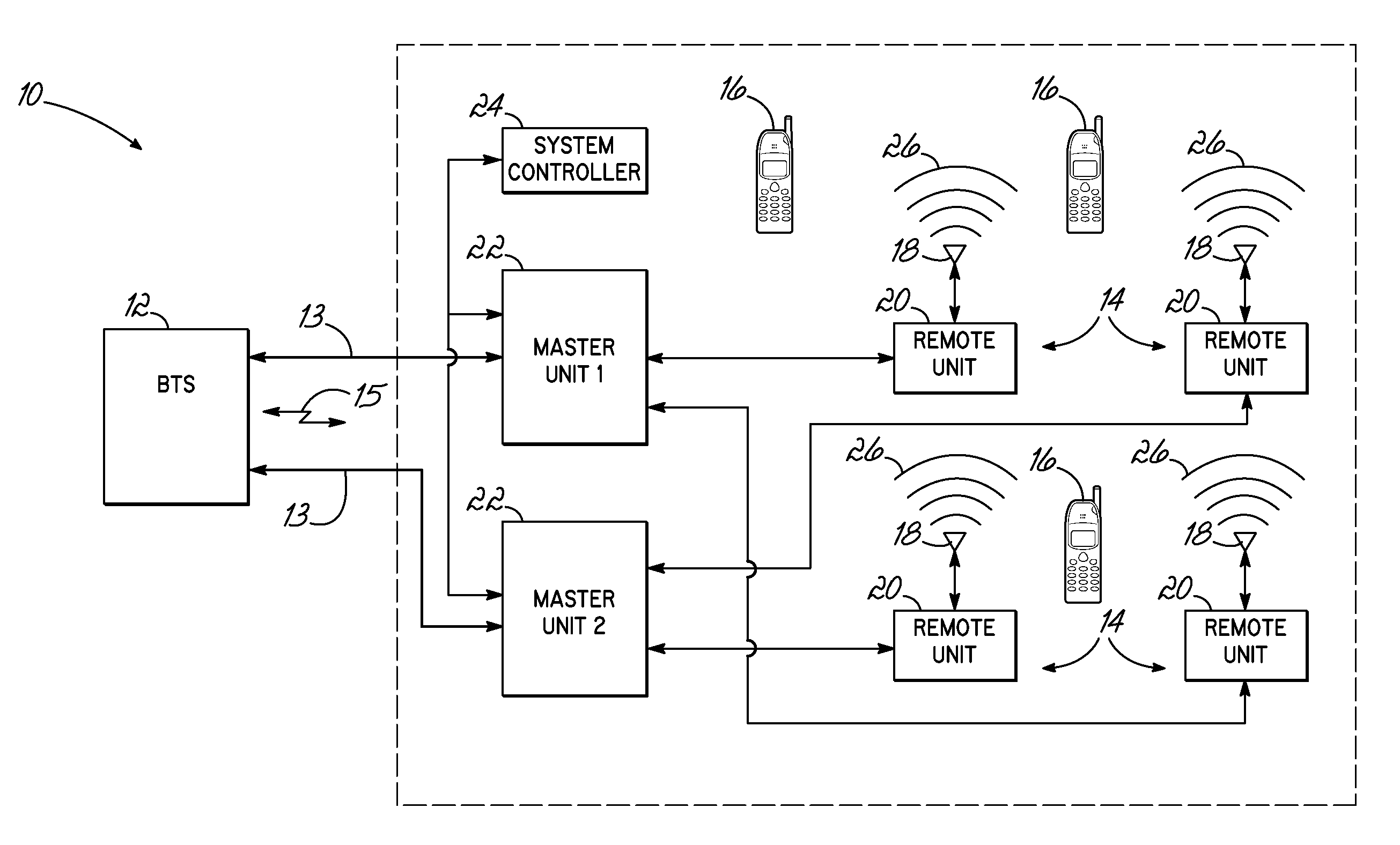
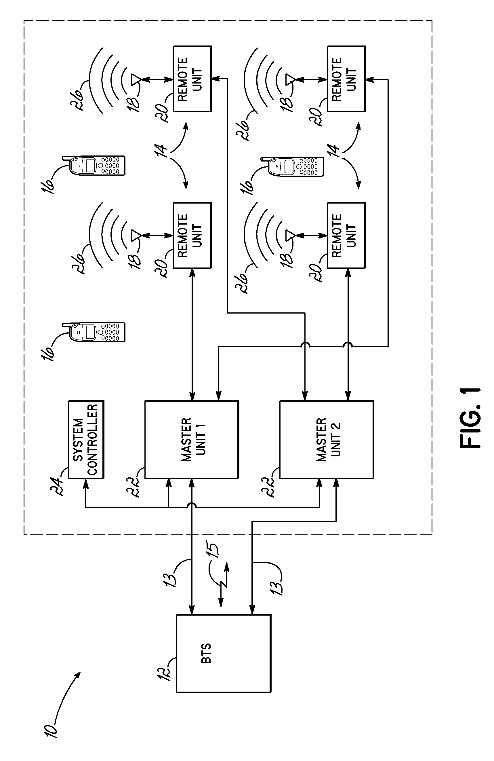
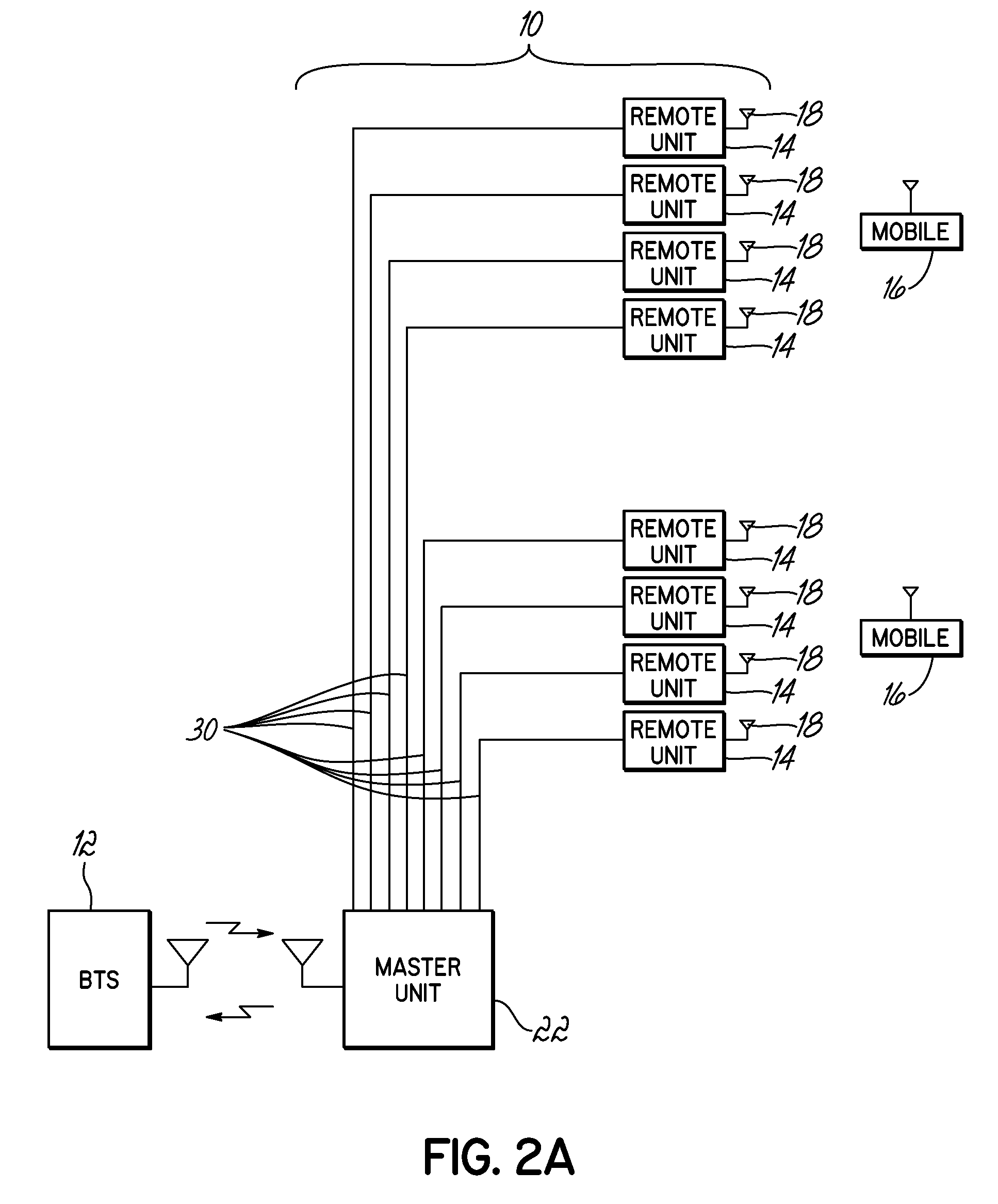
[0022]The present invention is directed to a method and apparatus for controlling uplink signal power in a distributed antenna system that has a master unit and a plurality of remote units. The master unit is coupled with a base station, and the remote units are coupled with the master unit. The invention includes monitoring of a noise condition of a distributed antenna system, and dynamically adjusting an uplink gain within the distributed antenna system, that is applied to uplink signals to a base station, based upon the monitored noise condition. In one exemplary embodiment, the number of active status remote units is determined, and the uplink gain is dynamically adjusted by increasing the uplink gain in response to a decrease in the number of remote units that are active status, and decreasing the uplink gain in response to an increase in the number of remote units that are active status. Other embodiments of the invention, as set forth herein, are also contemplated in the inve...


PUM


Abstract

A method and apparatus for controlling uplink signal power in a distributed antenna system 10 having a master unit 22 and a plurality of remote units 14 and coupled with a base station 12 includes monitoring a noise condition of the distributed antenna system. The invention dynamically adjusts an uplink gain within the distributed antenna system 10 that is applied to uplink signals to a base station 12, based on the monitored noise condition. Monitoring the noise condition in the distributed antenna system 10 includes monitoring one or more remote units 14 of the plurality of remote units and determining if the remote unit is active status or mute status and then. The uplink gain is increased in response to a decrease in the number of remote units that are active status and decreased in response to an increase in the number of remote units that are active status.

Description

CROSS-REFERENCE TO RELATED APPLICATIONS[0001]This application is a continuation of, and claims priority from International Application No. PCT / US2011 / 039592, filed Jun. 8, 2011, and entitled “Uplink Noise Minimization”, which, in turn, claims priority to U.S. Provisional Patent Application Ser. No. 61 / 352,851 filed Jun. 9, 2010, and entitled “Uplink Noise Minimization,” the applications and disclosures of which are incorporated herein by reference in their entireties.FIELD OF THE INVENTION[0002]The present invention relates generally to signal repeating systems, such as repeaters or distributed antenna systems, for wireless communications.BACKGROUND OF THE INVENTION[0003]In existing wireless technologies, signal repeating devices and systems, such as repeaters or distributed antenna systems (“DAS”), are used to extend the coverage of an overall wireless system beyond the range of traditional base stations. For example, an overall cellular or wireless communication system may consist...

Claims


Application Information

Patent Timeline
Patent Type & Authority Patents(United States)
IPC IPC(8): H04W52/52H04W52/14
CPCH04W52/52H04W52/146H04W88/085H04W52/46H04B7/0632H04W52/241H04W52/242H04B1/1027
Inventor PHILLIPS, FRED WILLIAMRANSON, CHRIS
Owner COMMSCOPE TECH LLC
Why Eureka
Try Eureka