Electrical connector plug having a metallic shield surronding a front edge of the plug

a technology of electric connectors and shields, which is applied in the direction of coupling devices, coupling protective earth/shielding arrangements, and two-part coupling devices, etc., can solve the problems of increasing coordination difficulties between computer manufacturers and accessory manufacturers, affecting the service life of the device, and not reaching a consensus on the specifications of the transmission interface of these accessory devices. , to achieve the effect of preventing elasticity loss, eliminating repair trouble, and increasing durability

Inactive Publication Date: 2015-10-13
ADVANCED CONNECTEK INC
View PDF5 Cites 10 Cited by
  • Summary
  • Abstract
  • Description
  • Claims
  • Application Information

AI Technical Summary

Benefits of technology

[0008]Embodiments of the invention provide an electrical connector plug and conductive wire, and an assembly provided with the same. The resilient electrical contact terminals are prevented from becoming a source of weaknesses of the USB plug. Various embodiments also provide protection to support the resilient contact terminals, so as to prevent structural damage due to excessive pressure. Such embodiments reduce the probability of malfunction of the resilient contact terminals. Even if they are accidentally damaged, the user can change them easily, so as to save both time and effort otherwise wasted by returning the host device to the manufacturer for maintenance.
[0009]Another aspect of embodiments of the invention is to provide an electrical connector plug and conductive wire, and an assembly provided with the same, which mounts the vulnerable resilient contact terminals on the USB plug so as to solve the problems of existing USB connectors, such as difficulty in replacement and related and wasting of time.
[0010]Another purpose of various embodiments of the invention is to provide an electrical connector plug and conductive wire, and an assembly provided with the same, which adds a metallic shield frame to the USB plug to provide additional protection for the vulnerable resilient contact terminal and that absorbs excessive external forces on the metallic shield frame. In this way, the metallic shield reduces the probability of structural damage to the resilient contact terminals due to external forces.
[0011]Another purpose of various embodiments of the invention is to provide an electrical connector plug and conductive wire, and an assembly provided with the same, which adds a metallic shield frame to the USB plug to provide crosstalk protection.
[0015]The electrical connector plug and conductive wire and assembly provided with same disclosed in this case mounts the resilient electrically conductive terminals of the USB socket on the USB plug, and provides a metallic shield frame to support the resilient contact terminals, preventing elasticity loss due to excessive pressure. In this way, additional protection is provided for the resilient contact terminals of the USB plug, so that they will not be easily damaged. Even if damaged, the user does not have to take the host computer in for repair, but simply needs to change the spare USB accessories, or even the conductive wire only. In this respect, the structure improves upon a significant drawback of the previous USB sockets and increases durability, eliminating the trouble of repair by the manufacturer.

Problems solved by technology

However, when multi-media computers initially came to rise, the manufacturers of these computers did not reach a consensus on the specifications for the transmission interfaces of these accessory devices.
Further, these different interface specifications often require the installation of corresponding drivers and then rebooting of the computing device prior to use.
This can be a source of significant inconvenience to consumers in terms of use, and also increases difficulties for computer manufacturers and accessory manufacturers in terms of coordination.
Since the original USB plug only fits one specific way in the USB socket, the USB socket can be damaged if the user inserts the USB plug in the wrong direction.
Further, it is somewhat troublesome to change and maintain the USB socket built into a host computer.
However, this structure is still a source of inconvenience for the user despite the fact that reverse plugging is avoided.
However, in addition to the above orientation problems, there are also some other factors that may damage USB sockets, such as the resilient contact terminals inside the socket.
However, USB 3.0 is more compact than the previous USB 1.0 or 2.0 versions, and as a result the structure of the resilient contact terminals is more delicate and fine due to the greater numbers.
If the resilient contact terminals are pressed improperly or used for a long time, the structure may be deformed, which can cause elastic fatigue or displacement.
This can lead to gaps, interruption in the electrical connections between the engaging terminals and the resilient contact terminals, and reduction in the effectiveness of the USB accessory device.
Consequently, the user cannot finish the desired goal using an external hard drive.
Some accessory devices also have large power requirements, and so they can occupy two neighboring USB sockets.
If one of these sockets is broken, it can be a source of great inconvenience to the computer operator.
However, it is quite difficult for the users to change a USB socket because it requires disassembling the computer and checking the motherboard.
Moreover, this kind of repair may take several days.
Nowadays, people rely on computers to such a degree that they may feel it is not worth it to spend so much time on a small component, which would delay their work or entertainment.

Method used


Image

  • Electrical connector plug having a metallic shield surronding a front edge of the plug
  • Electrical connector plug having a metallic shield surronding a front edge of the plug
  • Electrical connector plug having a metallic shield surronding a front edge of the plug

Examples


Embodiment Construction

[0026]The above statements related to embodiments of the invention, other technical aspects, features and benefits will be clearly presented in the detailed illustration for the preferred embodiments as shown in the diagrams. The embodiments of this case take a USB connector as examples. However, the technology of this case is not limited to the USB connectors, and can also be applied to other related products and connectors.

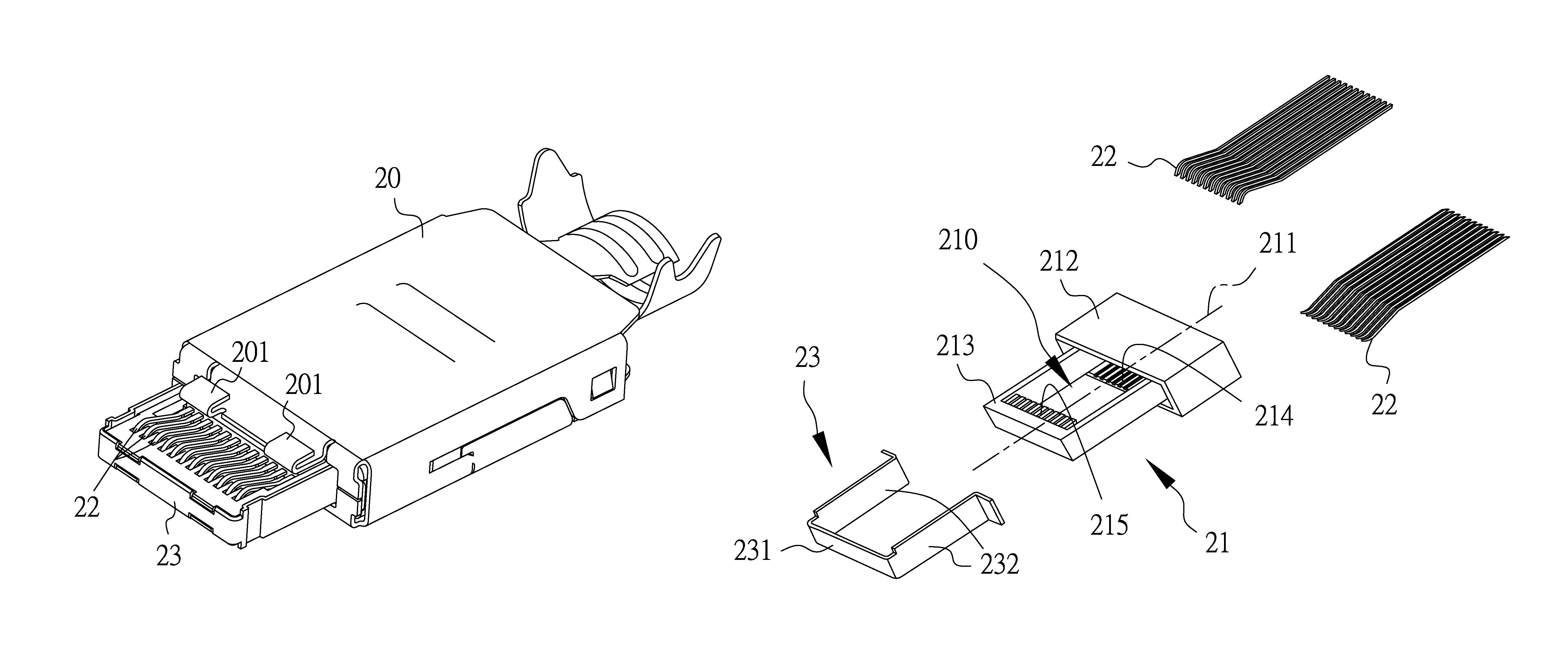
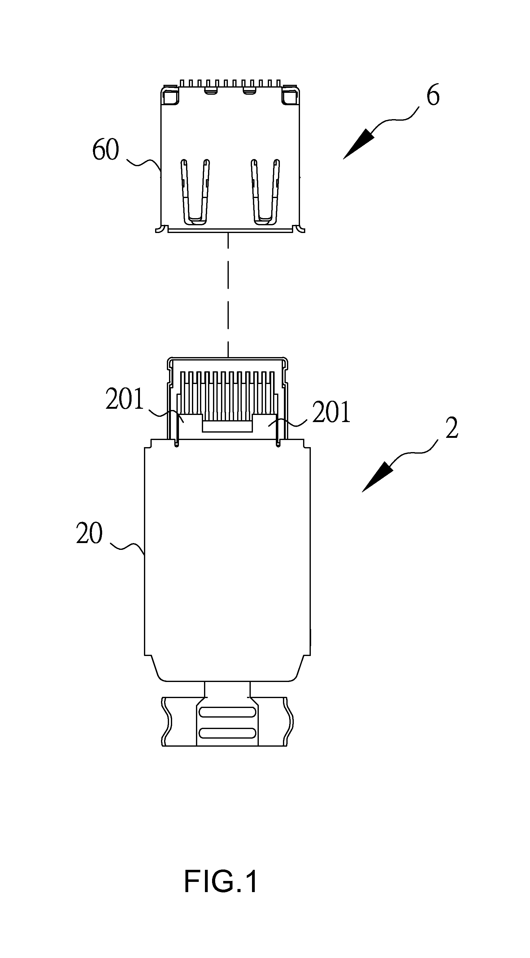
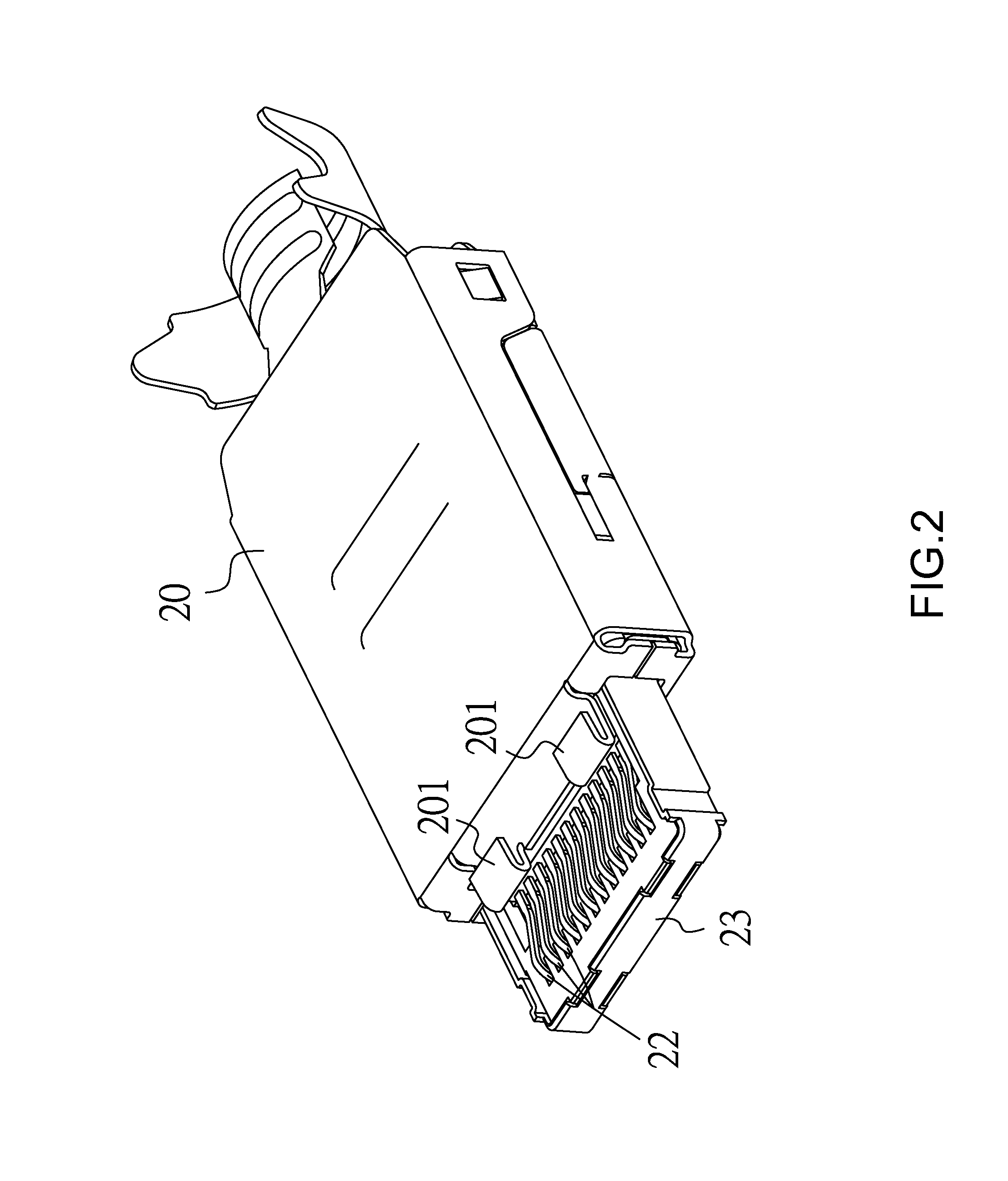
[0027]The first preferred embodiment of the invention is an electrical connector assembly, as shown in FIGS. 1 and 2. The electrical connector assembly is a USB connector assembly in this embodiment, having an electrical connector socket 6, which is a USB socket, and an electrical connector plug 2, which is a USB plug. When they are coupled and electrically connected together, an electrically conductive housing 20 of the electrical connector plug 2 is electrically connected to a casing 60 of the electrical connector socket 6 through at least one electrically con...


PUM


Abstract

An electrical connector plug has resilient contact terminals for electrical connection to an electrical connector socket. The electrical connector plug has an electrically conductive housing, and a dielectric shell and resilient contact terminals are mounted in the electrically conductive housing. The dielectric shell has a base portion and a front edge portion extending from the base portion. Two groups of resilient contact terminals are mounted on the dielectric shell and axially symmetrical to each other in the longitudinal direction, with each of the resilient contact terminals having a flat section and an upwardly protruding contact section. A metallic shield frame surrounds the front edge portion and is electrically connected to the electrically conductive housing, with the metallic shield frame having a front section and two lateral protective sections. The lateral protective sections have a height no less than that of the upwardly protruding contact sections.

Description

FIELD OF THE INVENTION[0001]The present invention relates to an electrical connector plug and conductive wire, and an assembly provided with the same.BACKGROUND OF THE INVENTION[0002]With the current prevalence of computers, people frequently connect various types of accessory devices to their computers so as to realize additional or desired functions. The most common of these accessory devices include external hard drives, portable disks, video and audio players, external power supplies, mice and keyboards. However, when multi-media computers initially came to rise, the manufacturers of these computers did not reach a consensus on the specifications for the transmission interfaces of these accessory devices. For example, many printers can only be connected to an LPT port; many MODEMs can only be connected to RS232 ports, several types of mice and keyboards can only connect to a PS / 2 ports, and so on. Further, these different interface specifications often require the installation o...

Claims


Application Information

Patent Timeline
Patent Type & Authority Patents(United States)
IPC IPC(8): H01R13/658H01R13/6596H01R13/6581H01R13/504H01R24/64
CPCH01R13/6596H01R13/6581H01R13/65802H01R24/64H01R13/504H01R13/658
Inventor KAO, YA-FENTSAI, YU-LUNHOU, PIN-YUANWANG, WEN-YUTSAI, WEN-HSIEN
Owner ADVANCED CONNECTEK INC
Why Eureka
Try Eureka