Methods of storing and moving proppant at location adjacent rail line

a technology of proppant and rail line, applied in the direction of stacking articles, liquid handling, ways, etc., can solve the problems of increasing the demand for proppant, increasing so as to reduce the risk of damage to the proppant supplier, the effect of reducing driver fatigue and enhancing the productivity of the proppant supplier

Active Publication Date: 2015-10-20
SANDBOX ENTERPRISES LLC
View PDF201 Cites 35 Cited by
  • Summary
  • Abstract
  • Description
  • Claims
  • Application Information

AI Technical Summary

Benefits of technology

The present invention is an apparatus for storing and delivering proppant at a well site. The apparatus includes a container with a hatch for introducing proppant and a flow gate for discharging proppant. The container has a longitudinal member and cross members positioned inside. The apparatus also includes a pneumatic bulk trailer for transporting proppant to the well site. The invention allows for easy transportation and unloading of proppant, as well as efficient delivery and storage at the well site.

Problems solved by technology

With the rise of hydraulic fracturing over the past decade, there is a steep climb in proppant demand.
Global supplies are currently tight.
However, it may break down or crush more readily under stress due to the relatively fewer grain-to-grain contact points to bear the stress often incurred in deep oil- and gas-bearing formations.
Typically, in any hydraulic fracturing operation, a large amount of such proppant is required.
Typically, it has been difficult to effectively store the proppant at the fracturing sites.
Additionally, it has been found to be rather difficult to effectively transport the proppant to the desired location.
Under such circumstances, the proppant is often exposed to adverse weather conditions.
This will effectively degrade the quality of the proppant during its storage.
Additionally, the maintenance of proppant in containers at the hydraulic fracturing site requires a large capital investment in storage facilities.
Often, the silos can have a cost of several million dollars.
Whenever such silos are used, there is a possibility of contamination of the proppant that is contained within the silo.
As such, lower quality proppant may be mixed with higher quality proppant so as to create an undesirable contaminated combination.
If the proppant is not available at the well site, then the fracturing operation can stall until such time that proppant is available.
In other circumstances, the operators of the fracturing operation may be forced to use lower quality proppant in order to continue the operation.
As such, the train is not able to be used for other purposes.
This adds additional cost to the fracturing operation.

Method used


Image

  • Methods of storing and moving proppant at location adjacent rail line
  • Methods of storing and moving proppant at location adjacent rail line
  • Methods of storing and moving proppant at location adjacent rail line

Examples


Embodiment Construction

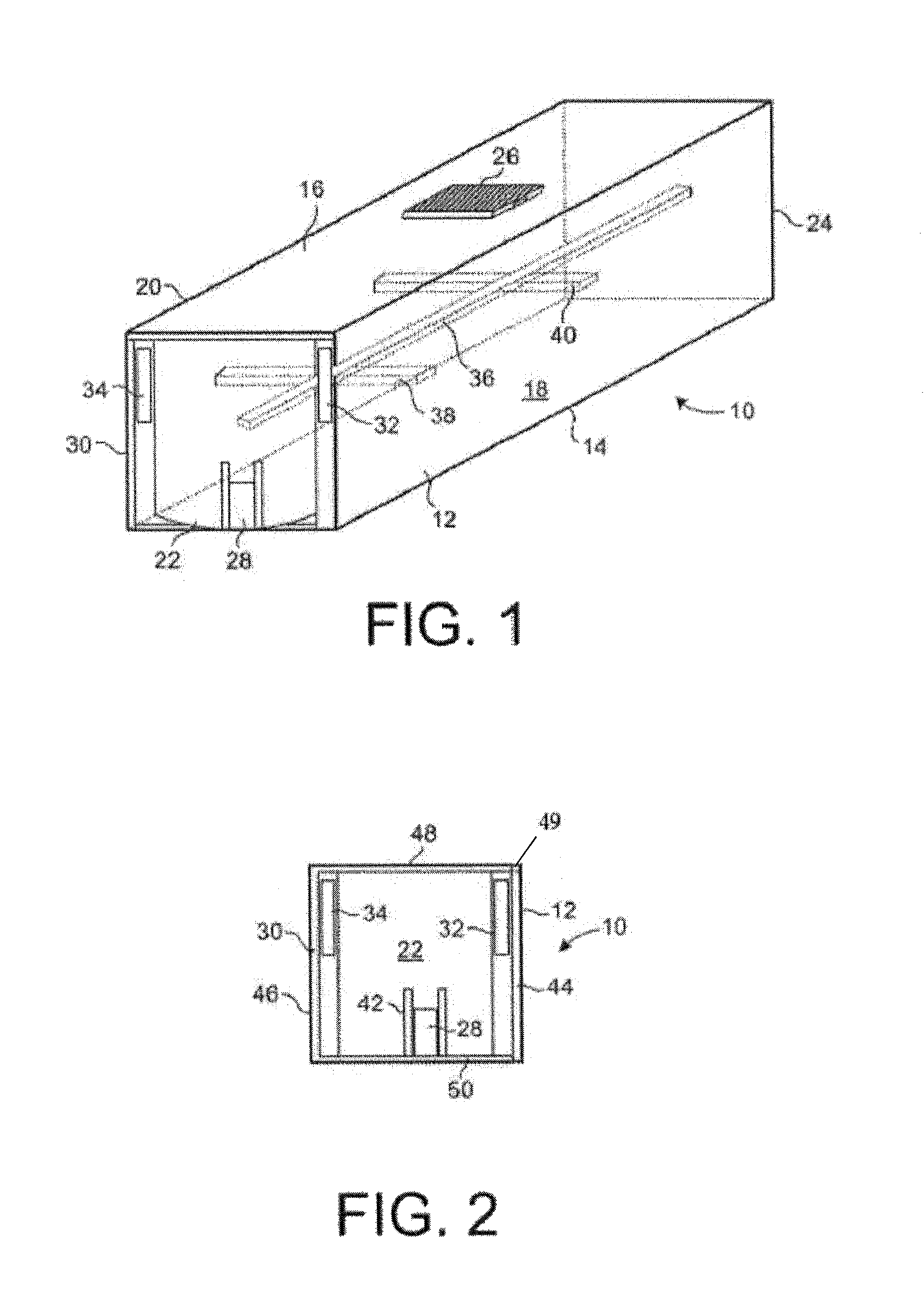
[0047]Referring to FIG. 1, there is shown the proppant storage apparatus 10 in accordance with the preferred embodiment of the present invention. The proppant storage apparatus 10 includes a container 12 having a bottom wall 14, a top wall 16, a pair of side walls 18 and 20 and a pair of end walls 22 and 24. The side wall 18 extends between the bottom wall 14 and the top wall 16. The side wall 20 also extends between the bottom wall 14 and the top wall 16 in generally spaced parallel relationship to the side wall 18. The end wall 22 extends between the bottom wall 14 and the top wall 16. Similarly, the end wall 24 extends between the bottom wall 14 and the top wall 16 and also between the side walls 18 and 20. The top wall 16 has a hatch 26 formed thereon. Hatch 26 is openable so as to allow proppant to be introduced into the interior volume of the container 12. A flow gate 28 is positioned on the end wall 22. The flow gate 28 is openable so as to allow the proppant to flow outwardl...


PUM


Abstract

A method of delivering proppant to a well site has the steps of transporting a load of proppant in a vessel to a desired location, moving the load of proppant from the vessel into a container so as to create a proppant-loaded container, unloading the proppant-loaded container into a pneumatic bulk trailer, and transporting the unloaded proppant in the pneumatic bulk trailer to well site. The container is placed onto a bed of a truck and moved in proximity to the vessel. The proppant-loaded container is placed onto a tilting mechanism and then tilted so that the proppant is discharged through a flow gate of a container into a hopper. The proppant in the hopper can then be conveyed to the pneumatic bulk trailer.

Description

RELATED APPLICATIONS[0001]This application is a continuation of U.S. patent application Ser. No. 14 / 310,648, filed Jun. 20, 2014, which claims the benefit of, is a continuation of, and is a U.S. National Stage of International Patent Appln. No. PCT / US13 / 32819, filed on Mar. 18, 2013, which claims the benefit of U.S. patent application Ser. No. 13 / 427,140 filed Mar. 22, 2012, now U.S. Pat. No. 8,622,251 issued on Jan. 7, 2014, which is a continuation-in-part of U.S. patent application Ser. No. 13 / 332,937 filed on Dec. 21, 2011, all of which are incorporated herein by reference in their entireties.BACKGROUND[0002]1. Field of the Invention[0003]The present invention relates to proppant storage containers. More particularly, the present invention relates to systems and methods for the delivery of proppant to a well site. More particularly, the present invention relates to containers as part of a system of storing proppant prior to delivery to a well site.[0004]2. Description of Related ...

Claims


Application Information

Patent Timeline
Patent Type & Authority Patents(United States)
IPC IPC(8): B60P1/64B65G65/23B65G67/24B65G65/30B65G57/20B65D88/70B65D90/00B65D90/34B61B1/00B65D88/56
CPCB61B1/005B65D88/56B65D88/70B65D90/008B65D90/34B65G57/20B60P1/6418B65G65/23B65G65/30B65G67/24B65G65/32B65D88/022B65G65/34B65G63/008
Inventor OREN, JOHN
Owner SANDBOX ENTERPRISES LLC
Why Eureka
Try Eureka