Shape memory cup seal and method of use

a memory cup and seal technology, applied in the field of wellbore isolation, can solve the problems of cup ripping or inverting

Active Publication Date: 2015-10-20
BAKER HUGHES INC
View PDF16 Cites 4 Cited by
  • Summary
  • Abstract
  • Description
  • Claims
  • Application Information

AI Technical Summary

Problems solved by technology

In deviated wellbores the rim is exposed to being dragged on the inside wall of the surrounding tubular which can cause the cup to either rip or invert if its open end is oriented in the same direction as for run in.

Method used


Image

  • Shape memory cup seal and method of use
  • Shape memory cup seal and method of use
  • Shape memory cup seal and method of use

Examples


Embodiment Construction

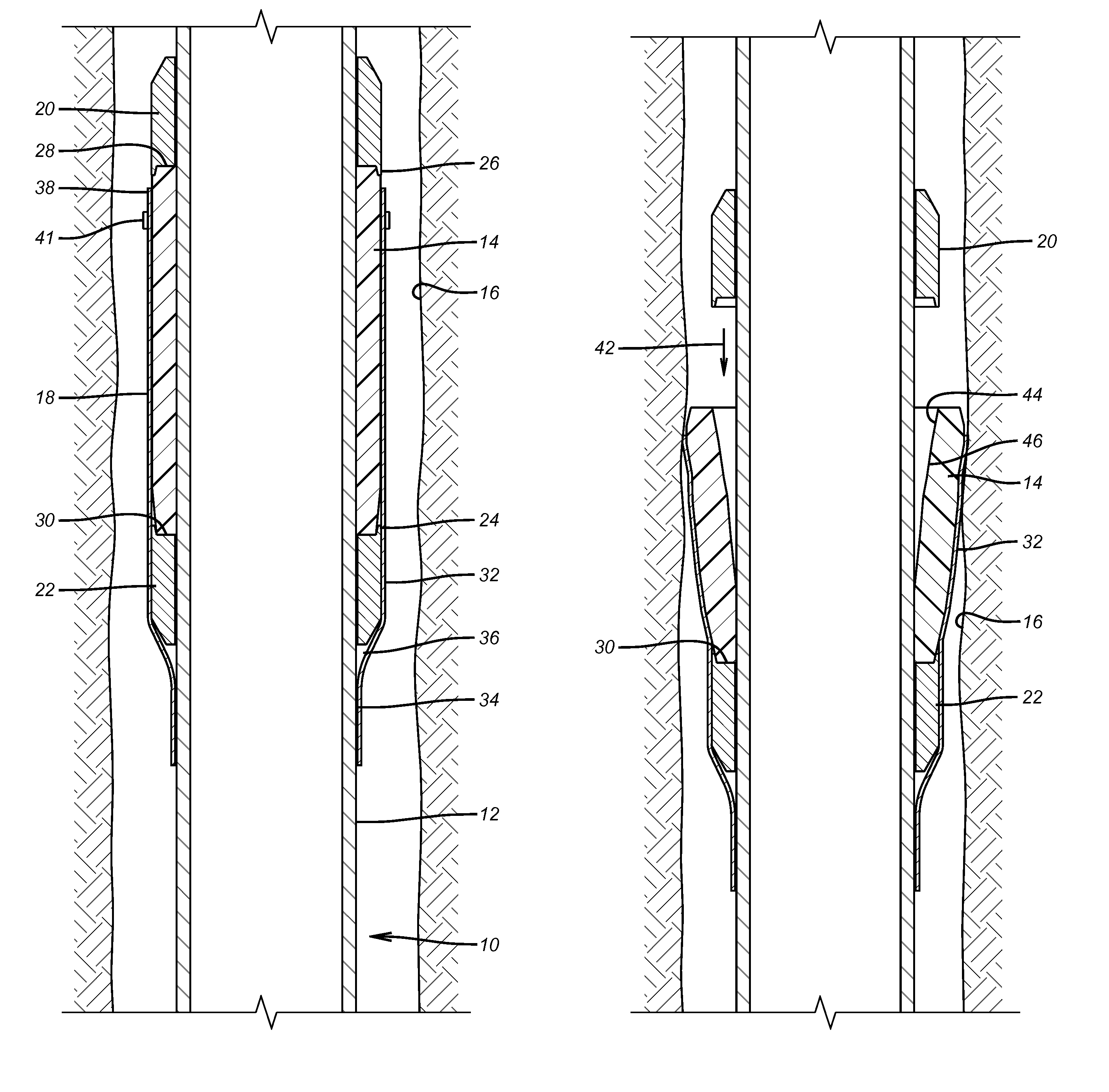
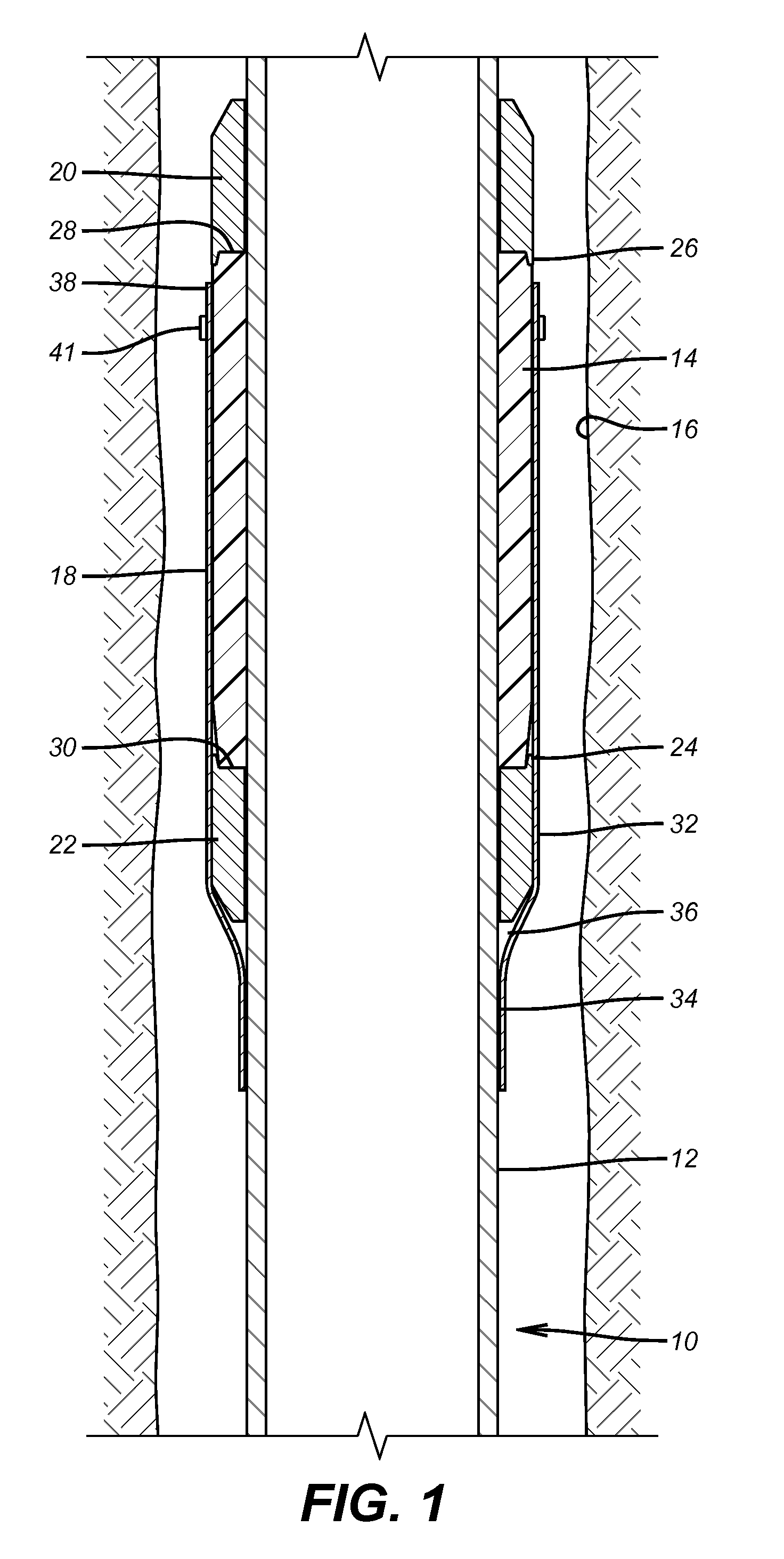
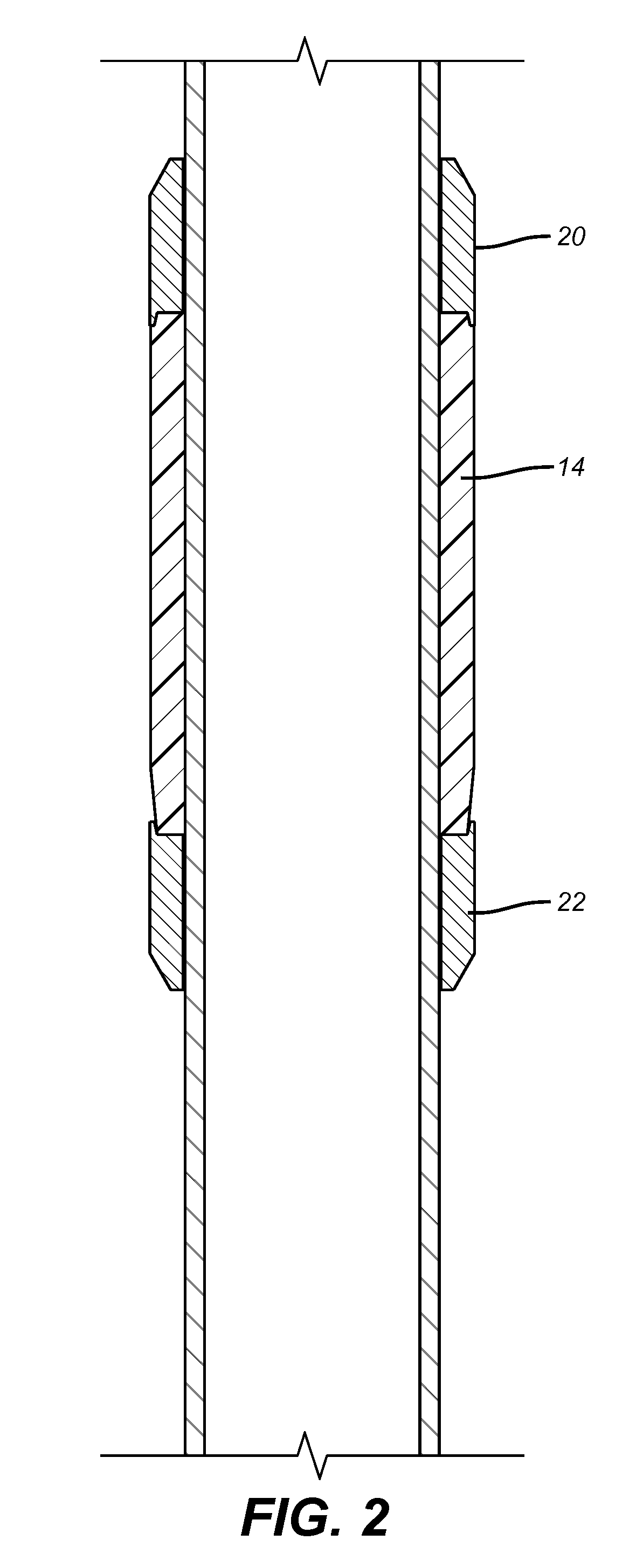
[0012]Referring to FIG. 1 a tubular string 10 acts as a mandrel 12 for the cup seal 14 in the run in condition. The cup seal 14 is initially fabricated from shape memory polymer to the desired dimension to seal against a surrounding borehole or tubular 16. For run in, the shape is reformed above the transition temperature and put into an annular cylindrical shape so that it contacts the mandrel 12 and has an outside diameter 18 that is as big or preferably smaller than the outside diameter of the end rings 20 and 22. End ring 22 has a peripheral axially oriented ring 24 while end ring 20 has a similar ring 26 that extends toward ring 24 but at a spaced location. The cup seal 14 in the run in position has an end 28 that is located between end ring 20 and mandrel 12. As heat is supplied preferably by well fluids and the cup seal 14 assumes its functional cup shape the upper end 28 simply moves out from behind the end ring 20 and out toward the borehole or tubular 16. Lower end 30 of t...


PUM


Abstract

A packer cup assembly uses a shape memory alloy packer cup reformed for run in into a cylindrical shape about a mandrel with opposed end rings that extend radially further out during run in to protect the cup. Upon application of a thermal stimulus the cup reverts to a functional cup seal shape by engaging the rim and parts of the cup to the surrounding wellbore. The shape change can also involve a shortened axial dimension that results in the cup shape moving away from the end ring to which it is unattached. The stimulus is provided with well fluids or artificially through heaters or other techniques. External elongated protective elements can be provided to overlay the cup seal during run and bend outwardly with the cup seal during reversion to its functional shape.

Description

FIELD OF THE INVENTION[0001]The field of the invention is wellbore isolation and more particularly thermally energized seals having a cup shape and related methods for running in such seals to avoid damage to them.BACKGROUND OF THE INVENTION[0002]Wellbore isolation needs arise in many contexts and a variety of sealing designs have been used to meet this need. Packers are run in to a desired location and then set with mechanical force or hydraulic pressure to extend slips for anchoring and a sealing element for sealing. Some packers are inflated to a sealing position using tubing pressure.[0003]Another type of isolation device is the cup seal. One such design shown in U.S. Pat. No. 4,424,865 uses the basic elastomer cup shape and includes a base and internal fingers of a shape memory alloy so that upon exposure to heat above a predetermined temperature, the ribs get stiffer and move the cup outwardly against the surrounding tubular to enhance the seal. Packer cups have also been form...

Claims


Application Information

Patent Timeline
Patent Type & Authority Patents(United States)
IPC IPC(8): E21B33/12E21B33/126
CPCE21B33/12E21B33/126E21B33/1208E21B33/1212
Inventor RAMON, MICHAEL
Owner BAKER HUGHES INC
Why Eureka
Try Eureka