
Cooling system for internal combustion engine

a technology for internal combustion engines and cooling systems, which is applied in the direction of liquid cooling, engine cooling apparatus, machines/engines, etc., can solve the problems of overheating of internal combustion engines and long time periods, and achieve the effect of correcting the character or nature of cooling water

Inactive Publication Date: 2015-10-20
TOYOTA JIDOSHA KK
View PDF15 Cites 0 Cited by
  • Summary
  • Abstract
  • Description
  • Claims
  • Application Information

AI Technical Summary

Benefits of technology

The system accurately estimates cooling water characteristics, enabling proper thermostat control to maintain stable engine operation by utilizing the specific heat properties of the cooling water, thereby preventing overheating and optimizing engine warming-up.

Problems solved by technology

Therefore, unless the thermostat is controlled depending on the character or nature of the cooling water, it is feared that the overheat of the internal combustion engine may be caused, or a long period of time may be required until the warming-up of the internal combustion engine is completed.

Method used


Image

  • Cooling system for internal combustion engine
  • Cooling system for internal combustion engine
  • Cooling system for internal combustion engine

Examples


first embodiment

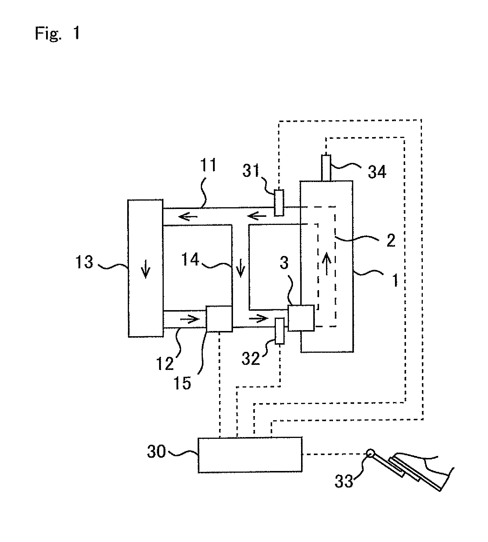
[0034]FIG. 1 shows a schematic arrangement of a cooling system for an internal combustion engine according to this embodiment. The internal combustion engine 1 shown in FIG. 1 is a water cooling type internal combustion engine.

[0035]A water jacket 2, which is provided to circulate the cooling water, is formed in the internal combustion engine 1. A first cooling water passage 11 and a second cooling water passage 12 are connected to the internal combustion engine 1. A radiator 13 and a bypass passage 14 are connected to the first cooling water passage 11 and the second cooling water passage 12.

[0036]The first cooling water passage 11 connects the outlet side of the water jacket 2 and the inlet side of the radiator 13. That is, the first cooling water passage 11 is the passage which is provided to discharge the cooling water from the water jacket 2. On the other hand, the second cooling water passage 12 connects the outlet side of the radiator 13 and the inlet side of the water jacket...

second embodiment

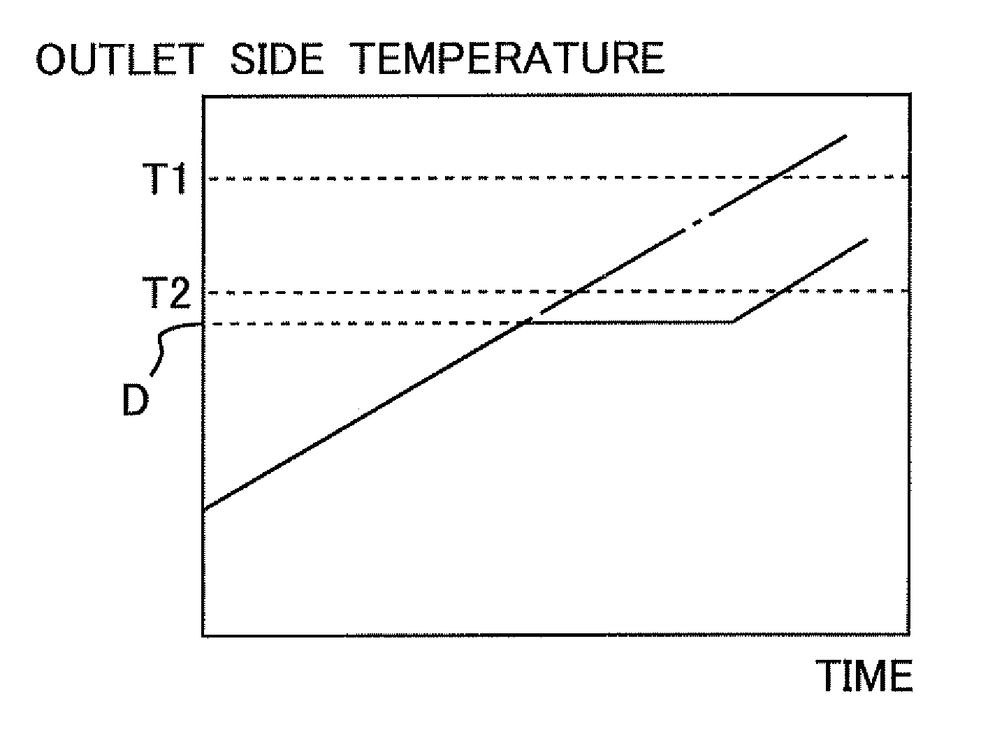
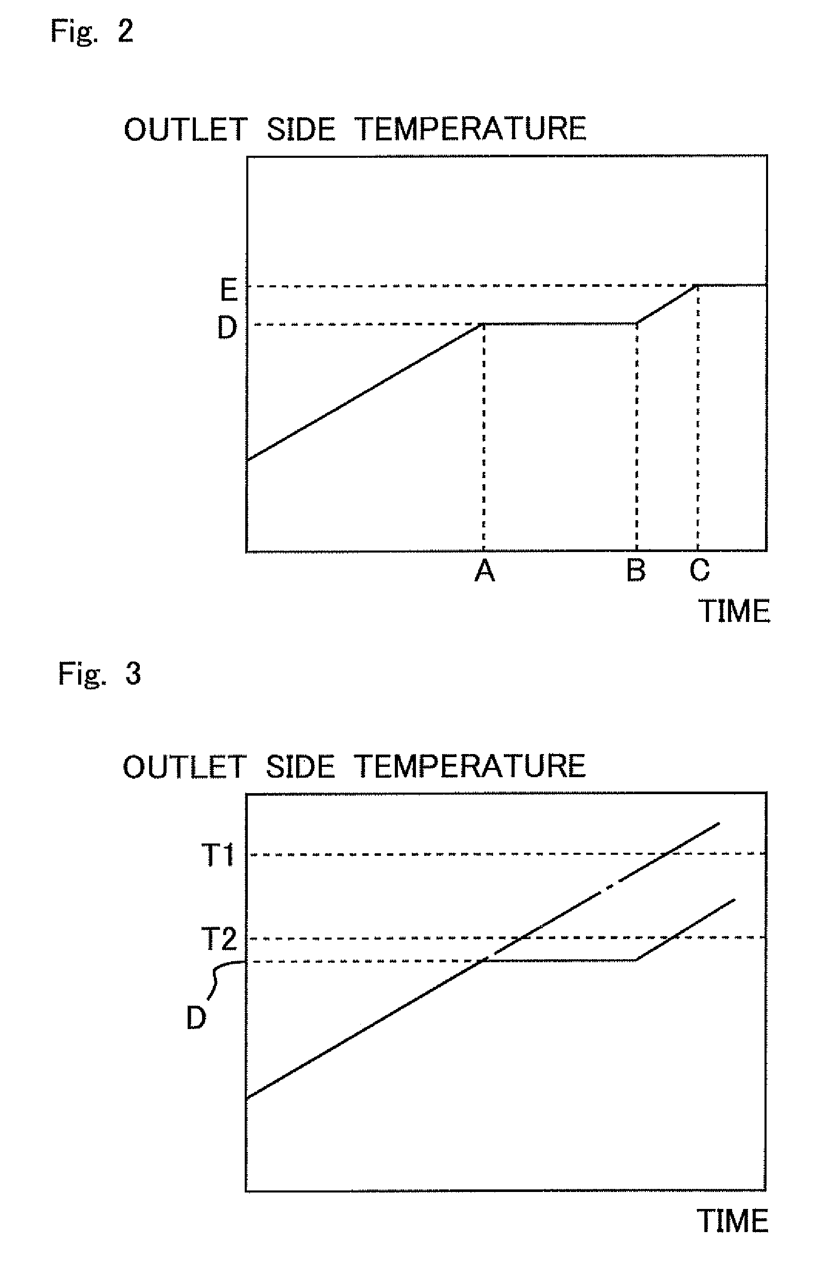
[0065]In this embodiment, it is judged whether or not the cooling water is deteriorated on the basis of the width of change of the cooling water temperature when ECU 30 controls the thermostat 15 in accordance with the valve opening temperature T2 of the thermostat 15 set in the first embodiment. For example, the other units or devices are the same as those of the first embodiment, any explanation of which will be omitted.

[0066]In this context, FIG. 5 shows a relationship among the temperature (inlet side temperature) of the cooling water allowed to flow into the internal combustion engine 1, the temperature (outlet side temperature) of the cooling water allowed to flow into the internal combustion engine 1, and the temperature of specific heat change D. In this context, in this embodiment, the valve opening temperature of the thermostat 15 is set so that the following relationship holds.

inlet side temperature

[0067]That i...


PUM


Abstract

The character or nature of cooling water is correctly estimated. A cooling system for an internal combustion engine includes a radiator, a bypass passage which bypasses the radiator, a thermostat, and a control unit which changes a valve opening temperature of the thermostat. The cooling system for the internal combustion engine further includes an estimating unit which forbids valve opening of the thermostat and which estimates the character of the cooling water on the basis of temperature transition of the cooling water provided in this state.

Description

TECHNICAL FIELD[0001]The present invention relates to a cooling system for an internal combustion engine.BACKGROUND ART[0002]Cooling water, in which the specific heat is changed at a predetermined temperature, is known (see, for example, Patent Document 1). The cooling water is constructed such that capsules, in which a substance to cause the phase transition is enclosed, are dispersed in the liquid. On the other hand, a technique is known, in which the cooling water temperature is raised by forbidding the valve opening of a thermostat (see, for example, Patent Document 2).[0003]In this context, the control of an electronic thermostat, which is performed in the same manner as in the conventional technique when the cooling water, in which the specific heat is changed at a predetermined temperature, is used in a system for controlling the electronic thermostat so that a preset cooling water temperature is provided, does not affirm that the characteristic, in which the specific heat of...

Claims


Application Information

Patent Timeline
Patent Type & Authority Patents(United States)
IPC IPC(8): F01P3/00F01P7/16
CPCF01P3/00F01P7/167F01P2025/30F01P2025/32
Inventor NAKATANI, KOICHIROYAMASHITA, AKIRASAODA, TAKENORI
Owner TOYOTA JIDOSHA KK
Learn More