Unlock instant, AI-driven research and patent intelligence for your innovation.

Image capturing device and image capturing method

a technology of image capturing and image, which is applied in the field of image capturing device and image capturing method, can solve the problem that the signal-to-noise ratio cannot be improved as expected

Active Publication Date: 2015-10-20
NEC CORP +1
View PDF10 Cites 2 Cited by
  • Summary
  • Abstract
  • Description
  • Claims
  • Application Information

AI Technical Summary

Benefits of technology

[0016]Therefore, an object of the present invention is to provide an image capturing device and an image capturing method that can solve the foregoing problem.
[0029]Thus, as an effect of the present invention, the signal-to-noise ratio can be improved compared to the related art in which the difference between one image captured during an ON period of a light source and one image captured during an OFF period thereof is calculated and the difference between the images is obtained.

Problems solved by technology

However, in the foregoing image capturing device, since only the difference between one piece of image data captured during the ON period of the light source and one piece of image data captured during the OFF period thereof, as a problem that would arise, the signal-to-noise ratio could not be improved as expected.

Method used


Image

  • Image capturing device and image capturing method
  • Image capturing device and image capturing method
  • Image capturing device and image capturing method

Examples


Embodiment Construction

[0047]Next, with reference to the accompanying drawings, exemplary embodiments of the present invention will be described.

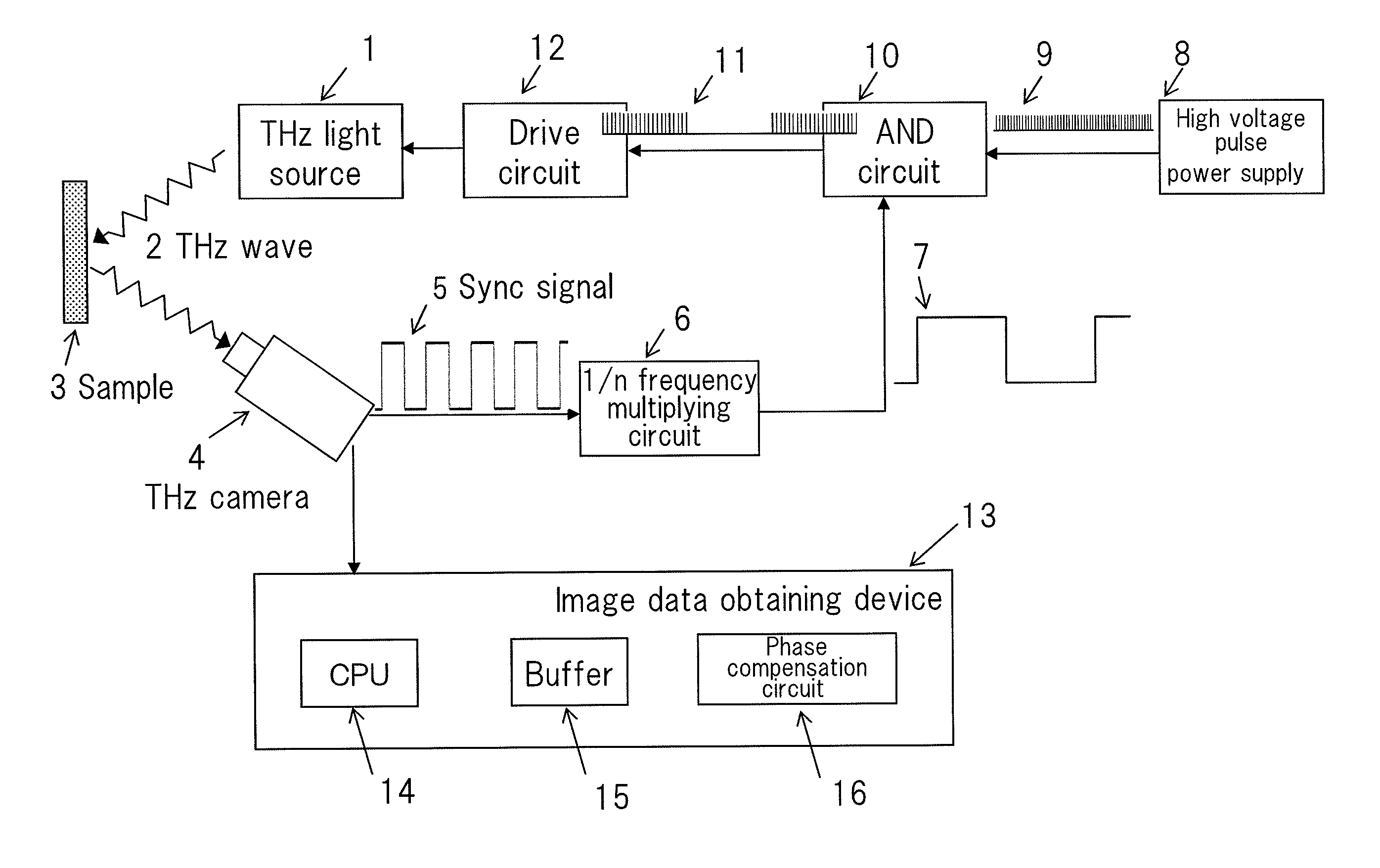
[0048]FIG. 4 shows a structure of an image capturing device according to an exemplary embodiment of the present invention.

[0049]As shown in FIG. 4, the image capturing device according to this exemplary embodiment has THz light source 1, THz camera 4, 1 / n frequency multiplying circuit 6, high voltage pulse power supply 8, AND circuit 10, drive circuit 12, and image data obtaining device 13. Image data obtaining device 13 has CPU 14, buffer 15, and phase compensation circuit 16.

[0050]In FIG. 4, CPU 14 is an example of a control unit; high voltage pulse power supply 8 is an example of a first pulse circuit; and 1 / n frequency multiplying circuit 6 is an example of a second pulse circuit.

[0051]THz wave 2 emitted by THz light source 1 is radiated to sample (measurement subject) 3 and then detected as a reflected wave or transmitted wave and captured as an image by THz...


PUM

PropertyMeasurementUnit
thermal time constantaaaaaaaaaa
repetition frequencyaaaaaaaaaa
frequencyaaaaaaaaaa

Abstract

The present invention is applied for an image capturing device having a light source and a camera that captures an image of a measurement subject placed in an optical path that lies between said camera itself and said light source. The image capturing device according to the present invention includes a control unit that subtracts a plurality of frame images captured by said camera during an OFF period of said light source from a plurality of frame images captured by said camera during an ON period of said light source, the number of frame images captured by said camera during the OFF period being the same as that number of frame images obtained by said camera during the ON period and integrates the differences between their images.

Description

[0001]This application is based upon and claims the benefit of priority from Japanese patent application No. 2011-070058, filed on Mar. 28, 2011, the disclosure of which is incorporated herein in its entirety by reference.BACKGROUND OF THE INVENTION[0002]1. Field of the Invention[0003]The present invention relates to an image capturing device that is provided with a light source and a camera and in which a measurement subject is placed in an optical path that lies therebetween, in particular, to an image capturing device that captures an image of a measurement subject in synchronization with ON / OFF states of the light source.[0004]2. Description of the Related Art[0005]Image capturing devices that are provided with a light source and a camera and in which a measurement subject is placed in an optical path that lies therebetween are known. In these image capturing devices, when an image of a measurement subject is captured in synchronization with the ON / OFF states of the light source...

Claims


Application Information

Patent Timeline
Patent Type & Authority Patents(United States)
IPC IPC(8): H04N9/47H04N7/18G01N21/3581G03B15/05G03B42/00G03B15/02H04N5/225H04N5/232H04N5/243
CPCG03B15/05G03B42/00G01N21/3581G03B2215/05G01N21/3586
Inventor ODA, NAOKIOHKUBO, SHUICHISUDO, TAKAYUKI
Owner NEC CORP