
Optical frequency locking method and device for optical data transmission

a technology of optical data transmission and optical frequency locking, which is applied in the direction of transmission, lasers, transmission monitoring/testing/fault-measurement systems, etc., can solve the problems of prohibitively expensive, arbitrary but fixed absolute frequency wavelength locking devices and arbitrary but fixed frequency spacings that are not readily commercially available, and generate new signals that are likely to interfere with a further signal of the wdm system. , to achieve the effect of large locking rang

Active Publication Date: 2015-10-20
ADVA OPTICAL NETWORKING SE
View PDF26 Cites 1 Cited by
  • Summary
  • Abstract
  • Description
  • Claims
  • Application Information

AI Technical Summary

Benefits of technology

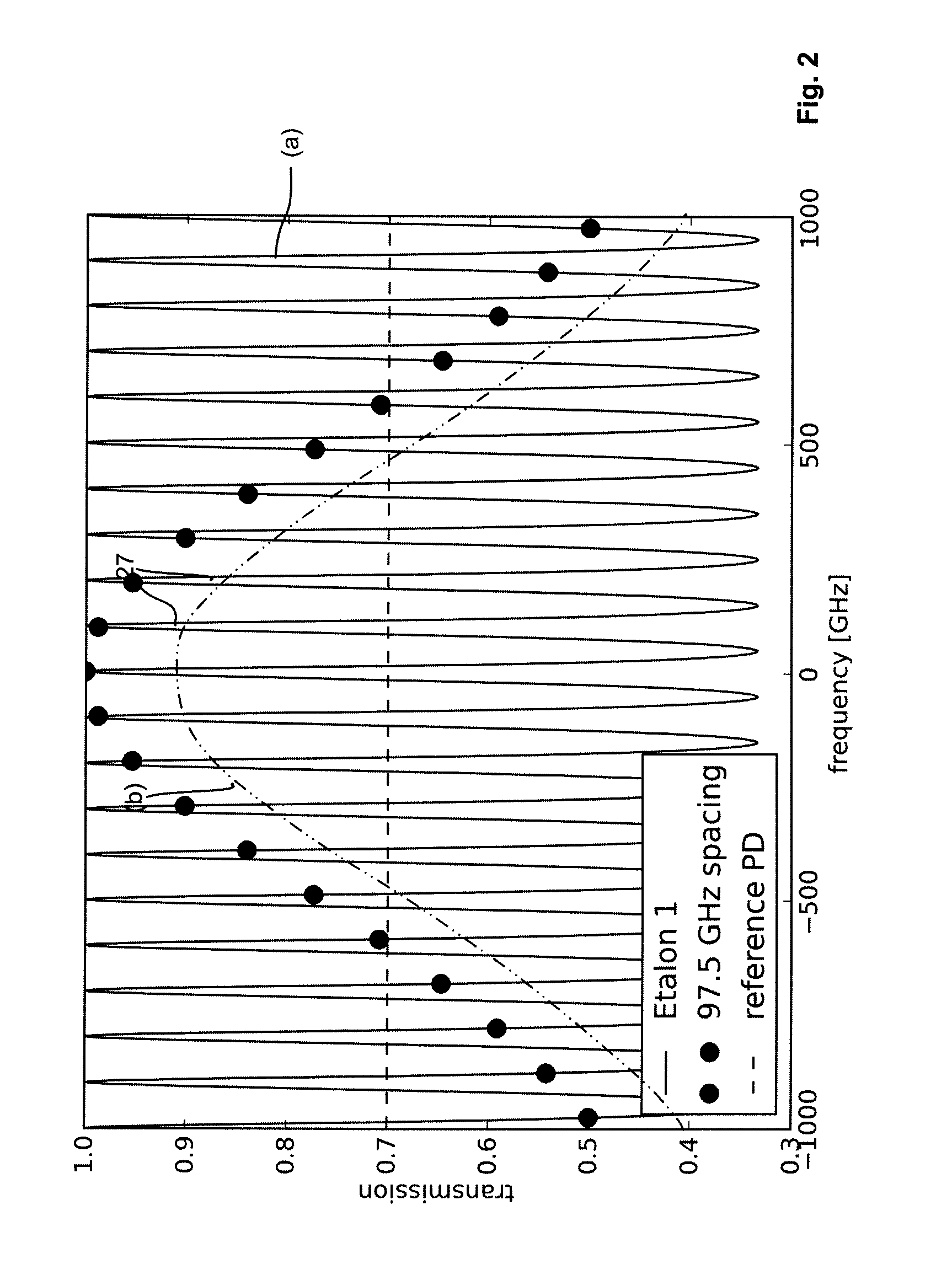
[0013]This method achieves a minimum locking range, which is typically larger than a quarter of the filter periodicity. This locking range can further be improved using the same devices, by comparing the ratio of the detected power values after the at least two optical filter devices and comparing this value to a value which would be detected when the signal is at the target frequency. To maximize the minimum locking range, for each target optical frequency the tuning method is determined (ratio of filter 1, ratio of filter 2, or ratio between filter 1 and filter 2).
[0019]In certain frequency ranges, using the ratio of two output signals for the tuning process is advantageous as a larger locking range is provided as compared to the use of the transfer functions of the at least two filter devices.

Problems solved by technology

However, in some applications, optical wavelengths or optical frequencies for the channel transmit signals are required, which do not match the ITU grid.
If the frequencies adhere to a fixed frequency grid, the generated new signal is likely to interfere with a further signal of the WDM system.
Unfortunately, wavelength-locking devices for arbitrary but fixed absolute frequencies and arbitrary but fixed frequency spacings are not readily commercially available, or they are prohibitively costly as it is necessary to manufacture optical filter devices having a periodicity matching the required frequency spacing in rather low numbers.
However, both variants require additional effort and costs.

Method used


Image

  • Optical frequency locking method and device for optical data transmission
  • Optical frequency locking method and device for optical data transmission
  • Optical frequency locking method and device for optical data transmission

Examples


Embodiment Construction

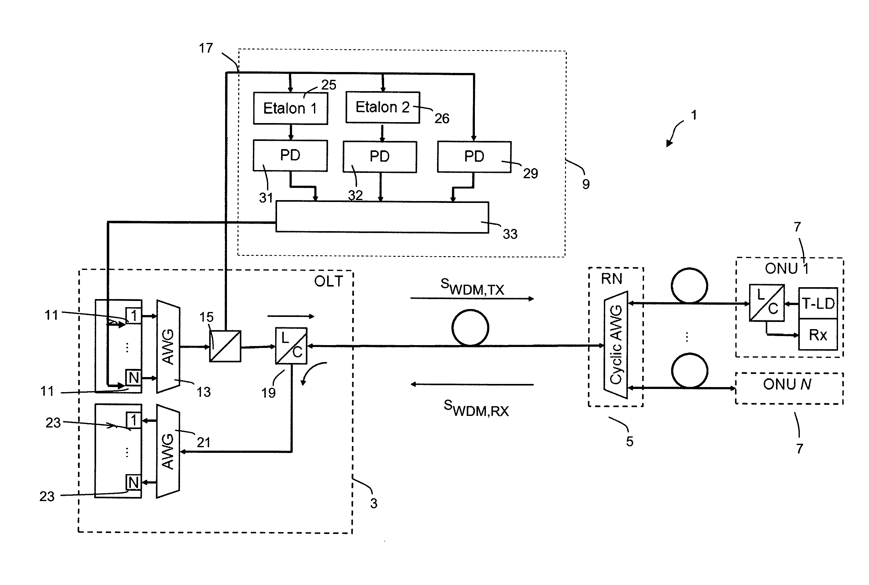
[0029]FIG. 1 shows a part of a complex fiber-optic data transmission system 1 comprising a central node in the form of an optical line terminal OLT, also designated by reference numeral 3, a remote node RN, also designated by reference numeral 5 and a number of N optical node units ONU 1 to ONU N, also designated by reference numerals 7, which may be provided at the customer locations. Further, the system includes an optical frequency locking device 9 that might be included within the OLT 3.

[0030]The OLT 3 includes an array of N tunable optical transmitter units 11, each being adapted to create an optical channel transmit signal at a given wavelength or optical frequency (due to the narrow optical spectrum of the transmit signals the term “(optical) frequency” will be used throughout the following description). The optical transmitter units 11 are preferably realized as laser diodes. The optical transmit signals created by the optical transmitter units 11 lie within a predetermined ...


PUM


Abstract

An optical frequency locking method tunes each of a plurality of narrow-band optical channel transmit signals (having arbitrary channel frequency spacings) to a dedicated optical channel frequency. The method includes tapping-off a portion of the optical power of the respective channel transmit signal and filtering the tapped-off channel transmit signal using at least one optical filter device. The method also includes monitoring, as an optical input signal, the optical power of the respective channel transmit signal supplied to the at least one optical filter device and, as an optical output signal, the optical power of the filtered channel transmit signal. The method further includes tuning, within a predetermined locking range for the dedicated optical channel frequency, the optical frequency of the respective channel transmit signal such that a predetermined value for the ratio of the output signal and the input signal is reached.

Description

TECHNICAL FIELD OF THE INVENTION[0001]The invention relates to an optical frequency locking method for tuning each of a plurality of narrow-band optical channel transmit signals to a dedicated optical channel frequency, the channel transmit signals having arbitrary channel frequencies within a transmission band spectrum. Further, the invention relates to an optical wavelength-locking device adapted to realize the corresponding method.BACKGROUND OF THE INVENTION[0002]In most optical data transmission applications using optical wavelength division multiplexing (WDM), the wavelengths of the optical transmitters (mostly lasers) need to be locked to dedicated channel wavelengths, for example according to the ITU wavelength grid with optical frequencies spaced by 100, 50, or 25 GHz. For this purpose, wavelength lockers are available using optical filter devices, like etalons, which are periodic with the ITU frequency spacing. The known methods for locking the wavelength or optical frequen...

Claims


Application Information

Patent Timeline
Patent Type & Authority Patents(United States)
IPC IPC(8): H01S5/0687H04B10/50H04B10/572H04B10/079H01S5/06H01S5/40
CPCH04B10/506H01S5/0687H04B10/0797H04B10/572H01S5/0617H01S5/4025
Inventor EISELT, MICHAELROPPELT, MARKUS
Owner ADVA OPTICAL NETWORKING SE
Learn More