
Phase discrimination circuit of delay phase-locked loop

A delay-locked loop and delay circuit technology, which is applied in the field of phase-detection circuits of delay-locked loops, and can solve the problems of inability to lock and small delay range of voltage-controlled delay chains.

Active Publication Date: 2020-07-14
SHANGHAI ANLOGIC INFOTECH CO LTD
View PDF5 Cites 0 Cited by
  • Summary
  • Abstract
  • Description
  • Claims
  • Application Information

AI Technical Summary

Problems solved by technology

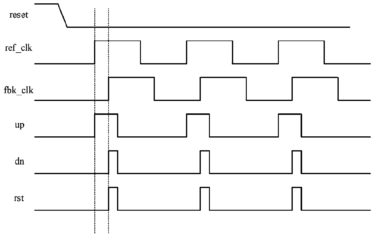
But if the initial delay value of VCDL is less than half of Tclk, or greater than three-half of Tclk, the DLL loop will be as follows Figure 5 Unable to lock or lock at multi-cycle as shown
In order to lock the DLL at the place where clk_out is delayed by one cycle relative to ref_clk, the delay range T_(d_vcdl) of the voltage-controlled delay chain should satisfy: 1 / 2T_clk

Method used


Image

  • Phase discrimination circuit of delay phase-locked loop
  • Phase discrimination circuit of delay phase-locked loop
  • Phase discrimination circuit of delay phase-locked loop

Examples


Embodiment Construction

[0025] In order to make the objectives, technical solutions and advantages of the present invention clearer, the technical solutions in the embodiments of the present invention will be described clearly and completely in conjunction with the accompanying drawings of the present invention. Obviously, the described embodiments are part of the present invention. Examples, not all examples. Based on the embodiments of the present invention, all other embodiments obtained by those of ordinary skill in the art without creative work shall fall within the protection scope of the present invention. Unless otherwise defined, the technical terms or scientific terms used herein shall be the ordinary meanings understood by those with ordinary skills in the field to which the present invention belongs. As used herein, "comprising" and other similar words mean that the elements or objects appearing before the word cover the elements or objects listed after the word and their equivalents, but ...


PUM


Abstract

The invention provides a phase discriminator circuit of a delay phase-locked loop, which comprises a frequency dividing circuit, a retiming circuit, a reference time delay circuit and a phase discriminator main body circuit. The frequency dividing circuit is connected with the retiming circuit, the retiming circuit is connected with the reference time delay circuit, and the reference time delay circuit is connected with the phase discriminator main body circuit. The phase discrimination circuit of the delay phase-locked loo comprises the frequency division circuit, the retiming circuit, the reference time delay circuit and the phase discriminator main body circuit, wherein the frequency division circuit, the retiming circuit and the reference delay circuit are added on the basis of the phase discriminator main body circuit; thus the delayed frequency division reference clock can be aligned with the frequency division feedback clock, and the locking range of the phase-locked loop is expanded.

Description

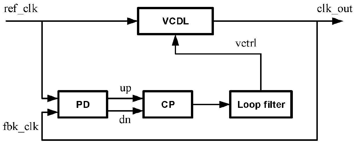
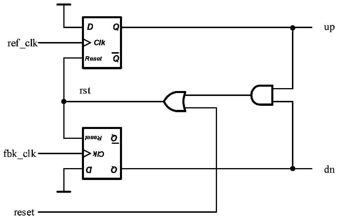
Technical field [0001] The present invention relates to the technical field of delay locked loops, in particular to a phase discriminating circuit of a delay locked loop. Background technique [0002] Delay lock loop (DLL) is widely used in high-speed data transmission, especially in double data rate (Double Data Rate, DDR) and serializer (SERializer, SERDES) systems with DLL to compensate for clock distribution The offset of the network. [0003] The typical structure of DLL is figure 1 As shown, including phase detector (PD), charge pump (chargepump, CP), loop filter (loop filter, LPF) and voltage control delay line (VCDL), reference clock ref_clk and The feedback clock fbk_clk obtained after the VCDL is the input of the PD, and the PD controls the charging and discharging of the LPF by the CP by comparing the phase difference between ref_clk and fbk_clk, thereby obtaining the control voltage vctrl of the VCDL. [0004] The typical structure of PD is figure 2 As shown, it includ...

Claims


Application Information

Patent Timeline
Patent Type & Authority Applications(China)
IPC IPC(8): H03L7/18H03L7/181
CPCH03L7/1803H03L7/181
Inventor 刘志华
Owner SHANGHAI ANLOGIC INFOTECH CO LTD
Learn More