Prosthesis for replacement of cartilage

a cartilage and bone joint technology, applied in the field of bone joint prosthesis, can solve the problems of needing to remove the entire meniscus, the failure mode of the knee joint, and the wear of the meniscus, so as to eliminate the wear and friction of the prosthetic meniscus

Inactive Publication Date: 2015-10-27
SUCCESSOR TRUSTEE OF THE EUGENE RIVIN LIVING TRUST +2
View PDF9 Cites 957 Cited by
  • Summary
  • Abstract
  • Description
  • Claims
  • Application Information

AI Technical Summary

Benefits of technology

[0006]The present invention is accordingly directed toward a meniscus prosthetic which successfully mirrors the function of the original cartilage pad or damaged portions of the pad, ideally to avoid the need for surgical removal of the entire knee joint. In a preferred embodiment of the invention, which will subsequently be disclosed in detail, the prosthesis comprises a pad formed by a single layer of streamlined elastomeric resilient elements disposed in a relatively compliant matrix. Compression forces and deformations in the functioning joint between the contact surfaces of femur and tibia bones are accommodated by nonlinear compression deformation of elastomeric streamlined, preferably spherical, elements which can be repeatedly compressed without failure up to 50%. Limited lateral relative displacements between femur and tibia in the functioning joint according to the instant invention are accommodated by limited rolling of the spherical compressed spherical elements, thus eliminating undesirable friction and wear of the prosthetic meniscus.

Problems solved by technology

The failure mode of the knee joint is usually wear of the meniscus due to sliding under high-contact forces and / or cracking of the cartilage caused mainly by local pressure concentrations while sliding.
Injury and disease can lead to the need to remove the entire meniscus, or portions thereof.

Method used


Image

  • Prosthesis for replacement of cartilage
  • Prosthesis for replacement of cartilage
  • Prosthesis for replacement of cartilage

Examples


Embodiment Construction

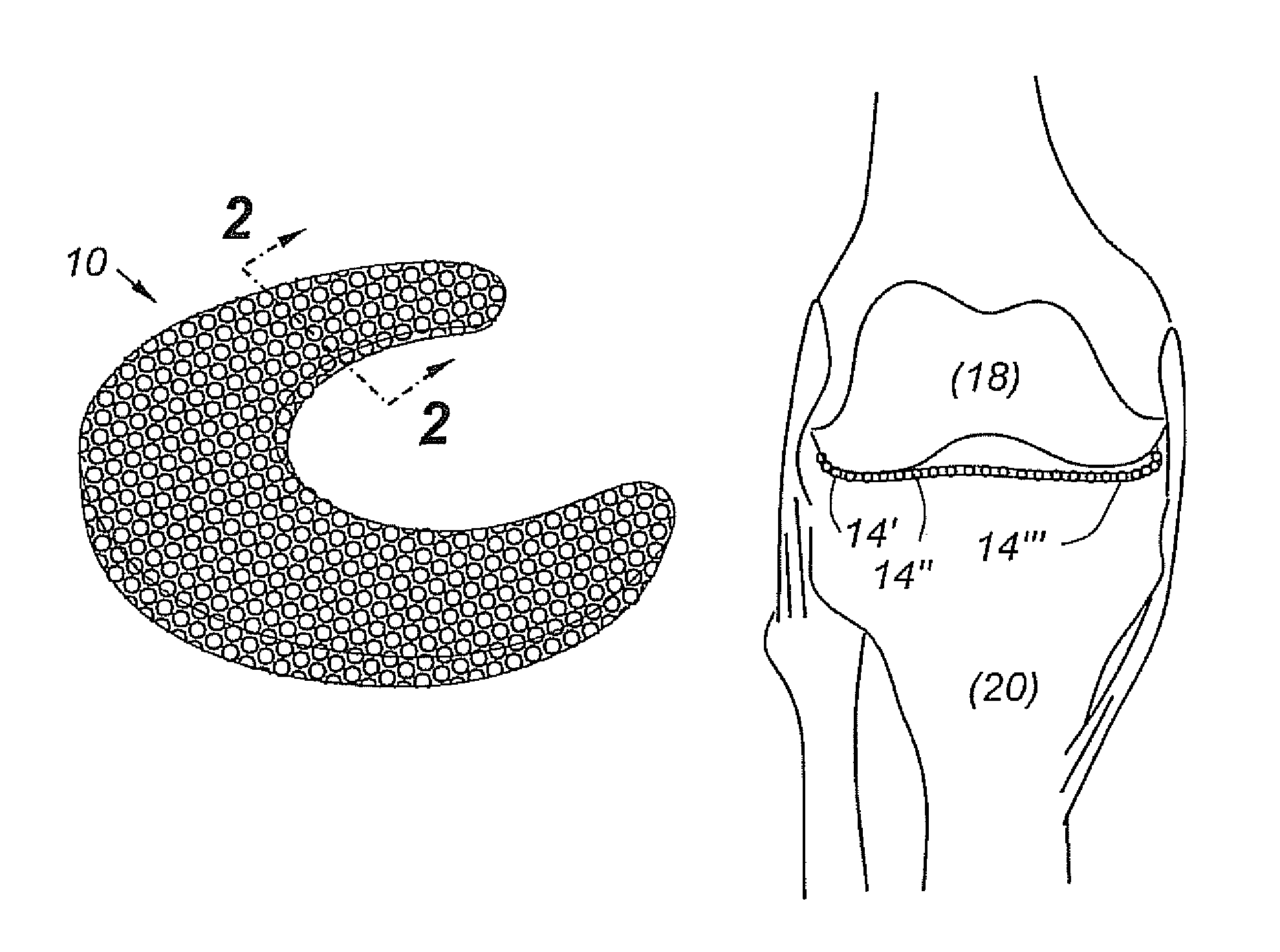
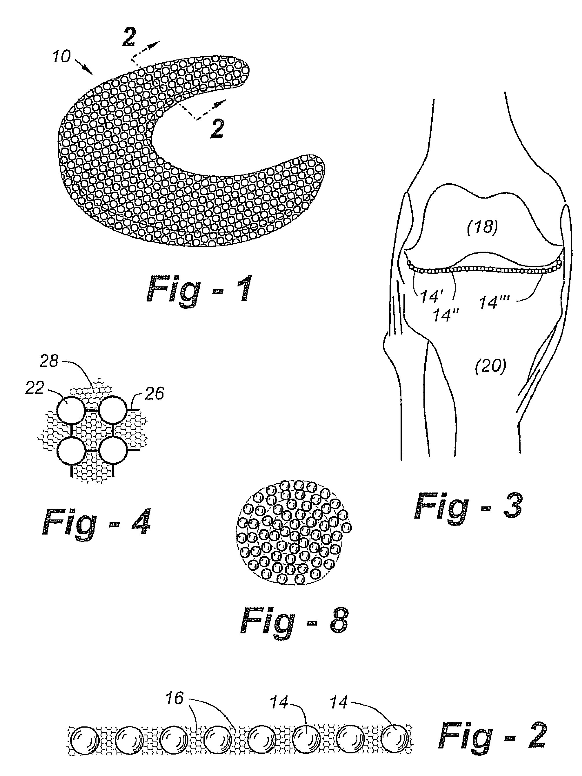
[0022]While the preferred embodiment of the invention involves use for the replacement of all or part of the cartilage layer of a knee joint, this and other embodiments of the invention can be employed in any of a similar mammalian joint such as a shoulder joint, hip joint, etc., which employs a cartilage sandwiched between two articulating bones which impose both compressive and shear forces on the associated soft tissue.

[0023]FIG. 1 is a perspective view of a prosthesis to replace a meniscus of a knee, not yet inserted between the contact surfaces of femur and tibia bones. The knee employs two similar meniscuses and a prosthesis for a lateral meniscus. The prosthesis comprises a pad generally indicated at 10. The pad, illustrated in cross section in FIG. 2, comprises a singular layer of elements 14, in this case compressible spherical elements having diameters which substantially equal the thickness of the pad 10 so that diametrically opposed points on each of the spherical elemen...


PUM


Abstract

A cartilage replacement or repair prosthesis comprises a layer of streamlined elastomer elements, preferably in the form of spheres, supported in a matrix material so that the radially opposed surfaces of the spheres are positioned on opposite surfaces of the layer and make contact with the opposed surfaces of the femur and tibia and the forces exerted between these bones extend through the streamlined elements. The matrix material has a substantially lower resistance to deformation than the spheres to control the position of the spheres relative to one another without significantly restraining their load-responsive deformation under forces exerted between the femur and tibia. The layer, with its elastomeric inserts, is sufficiently thin and flexible to allow it to be rolled for arthroscopic insertion into a knee joint.

Description

CROSS-REFERENCE TO RELATED APPLICATIONS[0001]This application claims priority of U.S. Provisional Patent Application Ser. No. 61 / 242,152 filed Sep. 14, 2009, which is incorporated herein by reference.FIELD OF THE INVENTION[0002]This invention relates to bone joint prostheses for replacing or repairing damaged cartilage and more particularly to prostheses employing streamlined elastomeric elements for transmitting the compressive and shear forces exerted on knees and other joints.BACKGROUND OF THE INVENTION[0003]Knee joints, which connect the tibia and the femur, are effected through a layer of cartilage, the meniscus, which has a very low friction coefficient but is sensitive to local pressure concentrations. The meniscus is subjected, in use, to compressive and sliding forces. The failure mode of the knee joint is usually wear of the meniscus due to sliding under high-contact forces and / or cracking of the cartilage caused mainly by local pressure concentrations while sliding. Injur...

Claims


Application Information

Patent Timeline
Patent Type & Authority Patents(United States)
IPC IPC(8): A61F2/38A61F2/30
CPCA61F2/3872A61F2/30965A61F2240/001
Inventor RIVIN, EVGENYKRASS, ALLEN M.
Owner SUCCESSOR TRUSTEE OF THE EUGENE RIVIN LIVING TRUST
Why Eureka
Try Eureka