Ultrasonic flowmeter with internal surface coating and method

a flowmeter and ultrasonic technology, applied in the direction of volume/mass flow measurement, measurement devices, instruments, etc., can solve the problems of black powder contamination, flow measurement error, affecting the accuracy of the meter in the manner, etc., and achieve the effect of limiting the buildup of contaminants

Active Publication Date: 2015-10-27
SENSIA LLC
View PDF17 Cites 7 Cited by
  • Summary
  • Abstract
  • Description
  • Claims
  • Application Information

AI Technical Summary

Benefits of technology

[0009]The invention described in this document may be used to prevent contaminants from affecting fluid flow through a flow passage of an ultrasonic flowmeter as well as the signals used by the flowmeter to determine the fluid flow through the flow passage, both of which can introduce error into the flow measurement. The invention, in accordance with certain embodiments, involves the presence of a non-stick coating on the wetted surfaces of the flowmeter which is believed to limit the buildup of contaminants on the wetted surfaces that could affect the fluid flow and the signals of the flowmeter.

Problems solved by technology

If a change in geometry occurs and is not corrected by calibration or some other means, then this may result in a flow measurement error.
It is known in the field of ultrasonic flow metering that alteration of the internal condition of an ultrasonic meter may affect the accuracy of the meter in the manner described above.
In gas pipelines black powder contamination is well known.
Furthermore, pipelines may also contain water, including salt water, which can lead to corrosion of the internal parts of ultrasonic flowmeter bodies.

Method used


Image

  • Ultrasonic flowmeter with internal surface coating and method
  • Ultrasonic flowmeter with internal surface coating and method
  • Ultrasonic flowmeter with internal surface coating and method

Examples


Embodiment Construction

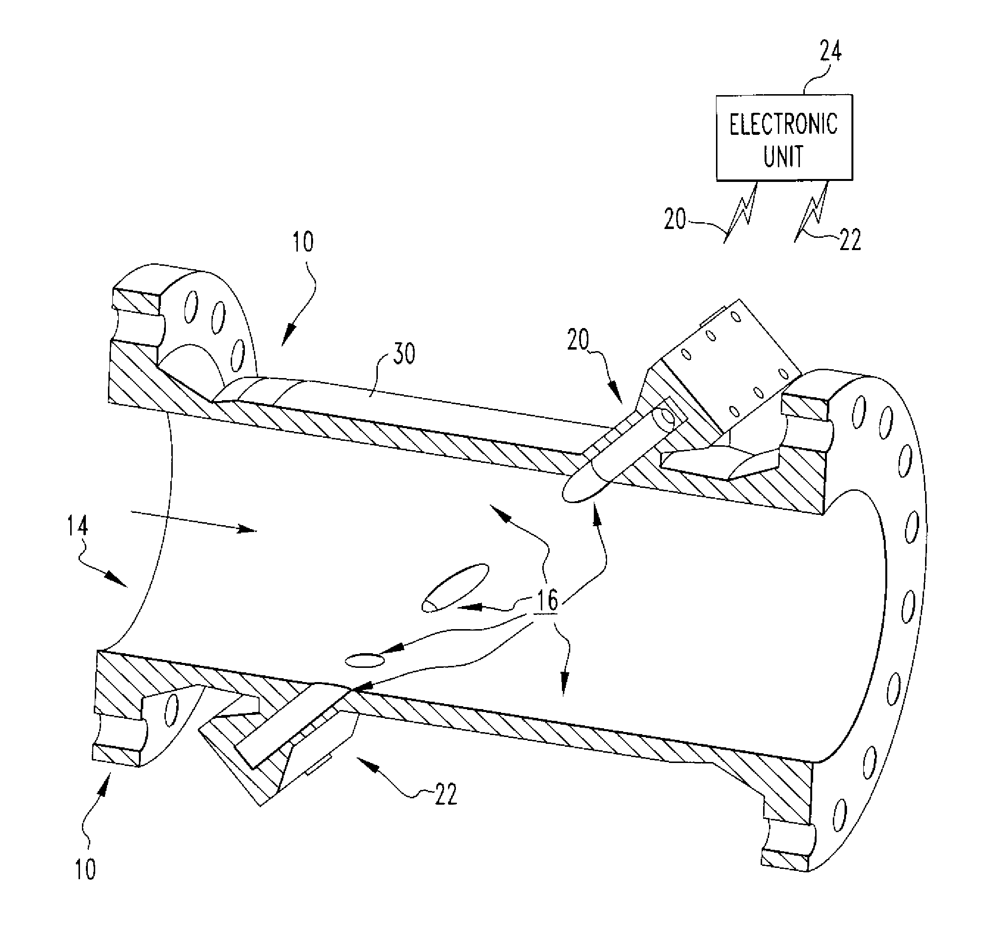
[0018]Referring now to the drawings wherein like reference numerals refer to similar or identical parts throughout the several views, and more specifically to FIGS. 1, 5 and 7 thereof, there is shown an exemplary ultrasonic flowmeter 10. The flowmeter 10 comprises a meter body 12 including a flow passage 14 having wetted surfaces 16 through which fluid flow is to be measured. The flowmeter 10 comprises a non-stick coating 18 adhered to the wetted surfaces 16 of the meter body 12. The flowmeter 10 comprises a first transducer 20 and at least a second transducer 22 arranged around the flow passage 14 to transmit and receive ultrasonic energy. The flowmeter 10 comprises an electronic unit 24 designed to generate and receive electronic signals from the transducers and to process the signals in order to compute information related to the fluid flow rate through the passage. For instance, the electronic unit 24 may be model number 280Ci produced by Cameron International Corporation.

[0019]...


PUM

PropertyMeasurementUnit
angleaaaaaaaaaa
temperatureaaaaaaaaaa
thicknessaaaaaaaaaa

Abstract

An ultrasonic flowmeter includes a meter body including a flow passage having wetted surfaces through which fluid flow is to be measured. The flowmeter includes a non-stick coating adhered to the wetted surfaces of the meter body. The flowmeter includes a first transducer and at least a second transducer arranged around the flow passage to transmit and receive ultrasonic energy. The flowmeter includes an electronic unit designed to generate and receive electronic signals from the transducers and to process the signals in order to compute information related to the fluid flow rate through the passage. A method for measuring fluid flow with an ultrasonic flowmeter. A method of making an ultrasonic flowmeter.

Description

FIELD OF THE INVENTION[0001]The present invention relates to the measurement of fluid flow with the use of transit time ultrasonic flowmeters. (As used herein, references to the “present invention” or “invention” relate to exemplary embodiments and not necessarily to every embodiment encompassed by the appended claims.) In particular, the present invention relates to the measurement of fluids where contaminants may be likely to adhere to or corrode the internal surfaces of the flowmeter.BACKGROUND OF THE INVENTION[0002]This section is intended to introduce the reader to various aspects of the art that may be related to various aspects of the present invention. The following discussion is intended to provide information to facilitate a better understanding of the present invention. Accordingly, it should be understood that statements in the following discussion are to be read in this light, and not as admissions of prior art.[0003]Transit time ultrasonic flowmeters function by measur...

Claims


Application Information

Patent Timeline
Patent Type & Authority Patents(United States)
IPC IPC(8): G01F1/66G01F15/00G01F15/14
CPCG01F1/662G01F15/006G01F15/14Y10T29/49007G01F1/66
Inventor BROWN, GREGOR J.AUGENSTEIN, DONALD R.HASTINGS, CALVIN R.FREUND, JR., WILLIAM R.
Owner SENSIA LLC
Why Eureka
Try Eureka