
Technique for cylindrical part inner surface inspection

a technology for inner surfaces and cylindrical parts, applied in the field of system and method for inspecting the inner surface of cylindrical parts, can solve the problems of high cost of manual inspection process, high cost, and high chance of overlooking, and achieve the effects of low cost, low cost, and reliable inspection process

Inactive Publication Date: 2015-10-27
FEDERAL MOGUL MOTORPARTS LLC
View PDF11 Cites 0 Cited by
  • Summary
  • Abstract
  • Description
  • Claims
  • Application Information

AI Technical Summary

Benefits of technology

The present invention is a system and method that allows for the reliable and cost-efficient detection of defects on the inner surfaces of parts. It provides high-resolution imaging with minimal distortion, and can inspect parts of different sizes using a single mirror. The system can automatically identify defects within a few hundred micrometers. Compared to prior art methods, the invention reduces the risk of overlooking defects and sends fewer defective parts to customers. The inspection time for each part is typically less than 10 seconds, which is faster than previous methods.

Problems solved by technology

The costs associated with this manual inspection process add up to hundreds of thousands of dollars each year.
Further, a single human inspector is typically required to inspect thousands of cylindrical parts each day.
Thus, chances of overlooking defects due to physical or mental fatigue, or inability to see the defects, and consequently shipping a defecting part to a customer are high.
However, the techniques used to inspect the inner surface either require the camera to be disposed inside the cylindrical part or require a conical mirror.
Thus, images acquired typically have low resolution and distortion.
In addition, the position of the camera and light source must be adjusted numerous times to acquire images of the entire inner surface, which is burdensome and time consuming.
Further, the conical mirror typically causes distortion in the image due to compressed pixels.

Method used


Image

  • Technique for cylindrical part inner surface inspection
  • Technique for cylindrical part inner surface inspection
  • Technique for cylindrical part inner surface inspection

Examples


Embodiment Construction

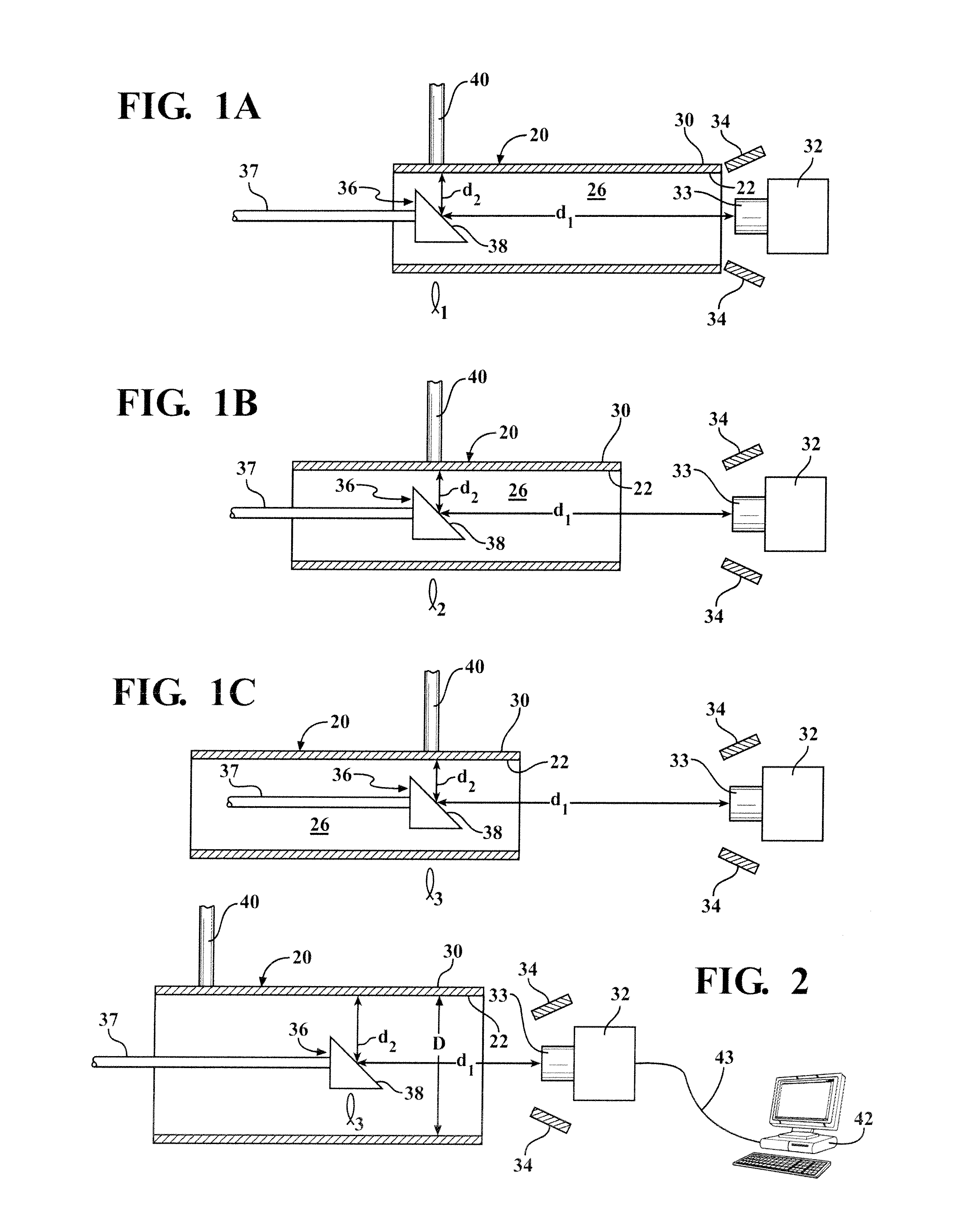
[0014]Referring to the Figures, a system and method for inspecting cylindrical parts 20 is generally shown in schematic drawings of FIGS. 1A-1C.

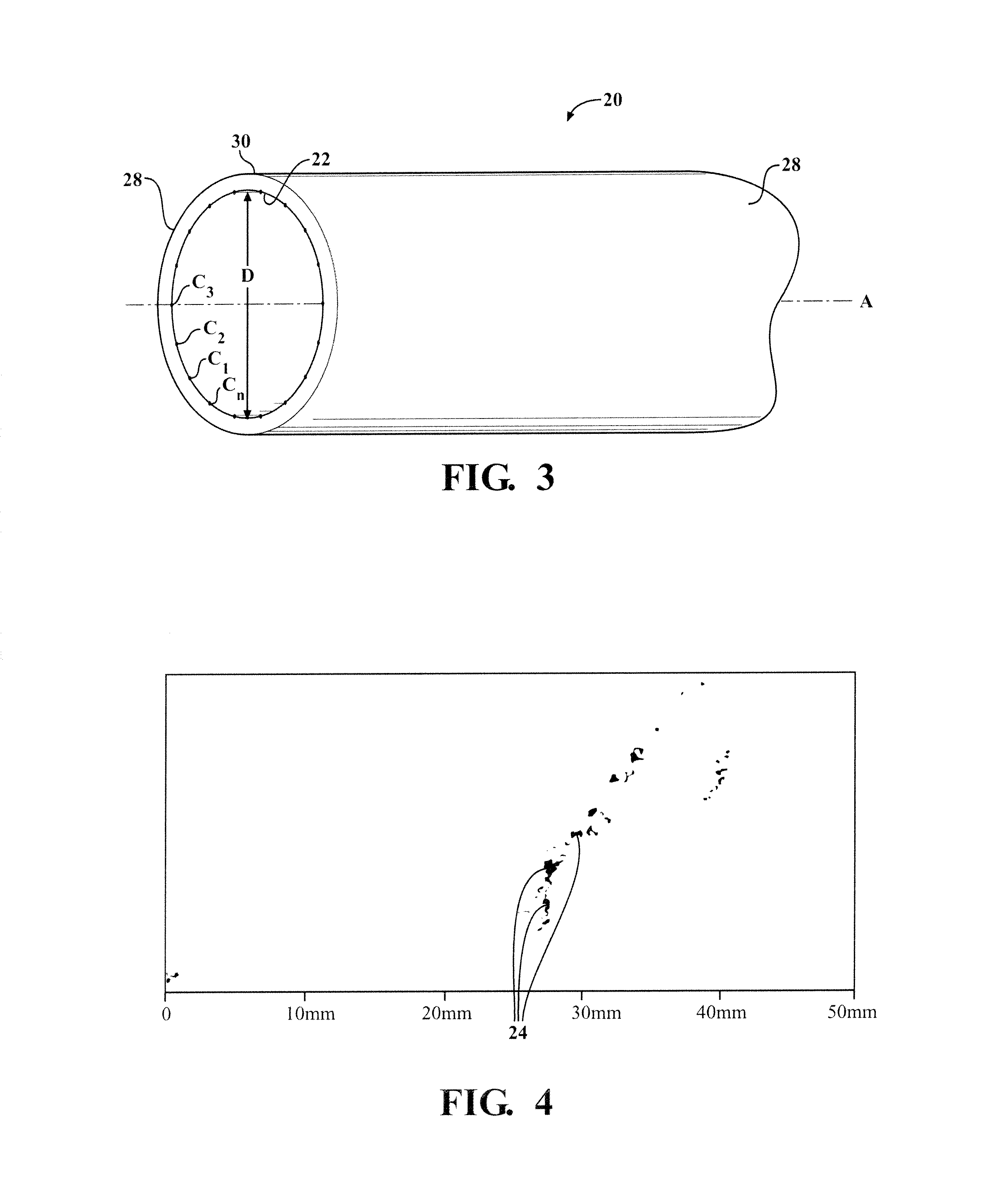
[0015]The system includes the plurality of cylindrical parts 20, such as cylinder liners for internal combustion engines. The cylindrical parts 20 are typically in the possession of a manufacture and are being prepared for shipping to a customer. The manufacturer will employ the system and method to inspect inner surfaces 22 of the cylindrical parts 20 for defects 24 or flaws prior to shipping the cylindrical parts 20 to the customer. Each of the cylindrical parts 20 includes the inner surface 22 extending circumferentially around a center axis A and presenting a bore 26 between opposite ends 28. The cylindrical part 20 also includes an outer surface 30 facing opposite the inner surface 22. The inner surface 22 of each cylindrical part 20 presents an inner diameter D between the opposite ends 28, as shown in FIG. 3.

[0016]The system includes ...


PUM

PropertyMeasurementUnit
angleaaaaaaaaaa
inner diameteraaaaaaaaaa

Abstract

A system and method for inspecting inner surfaces (22) of cylindrical parts (20) includes a line scan camera (30), a pair of light emitting diodes each directing light toward the inner surface (22), and a mirror (36) disposed in the cylindrical part (20) at a 45 degree angle relative to the inner surface (22). The camera (30) and mirror (36) remain in a fixed position while the cylindrical part (20) rotates continuously about a center axis (A) and the images are acquired. The cylindrical part (20) is then moved laterally along the center axis (A) and the images are again acquired as the cylindrical part (20) rotates about the center axis (A). An unwrapped display of the inner surface (22) is generated and used to automatically identify defects (24) on the inner surface (22).

Description

BACKGROUND OF THE INVENTION[0001]1. Field of the Invention[0002]This invention relates to a system and method for inspecting inner surfaces of cylindrical parts, such as cylinder liners for internal combustion engines.[0003]2. Description of the Prior Art[0004]Cylindrical parts, such as heavy-duty liners for internal combustion engines, are inspected manually by humans for subtle defects, such as cracks and porosity defects, in an effort to avoid shipping defective parts to a customer. The costs associated with this manual inspection process add up to hundreds of thousands of dollars each year. Further, a single human inspector is typically required to inspect thousands of cylindrical parts each day. The cylindrical parts are heavy, and subtle defects, such as those less than 200 microns, as well as defects located near the center of the cylindrical parts, are hardly visible to the naked eye. Thus, chances of overlooking defects due to physical or mental fatigue, or inability to see...

Claims


Application Information

Patent Timeline
Patent Type & Authority Patents(United States)
IPC IPC(8): H04N7/18G01N21/954
CPCG01N21/954
Inventor SHUKLA, SALIL
Owner FEDERAL MOGUL MOTORPARTS LLC
Learn More