
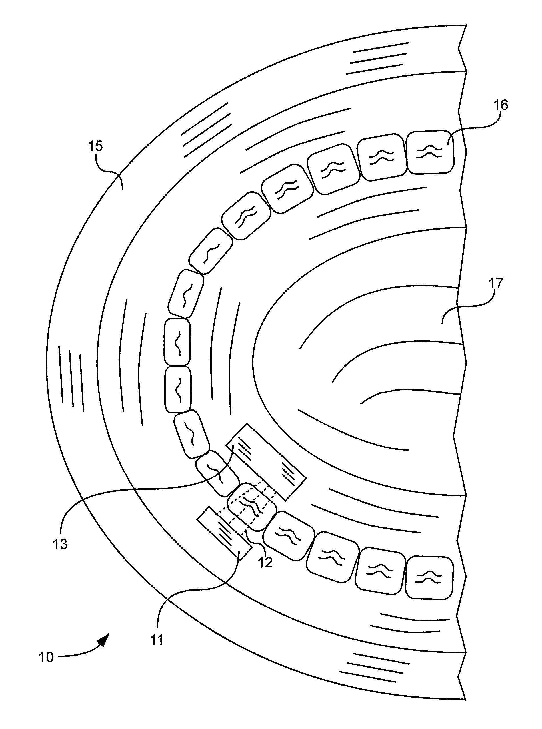
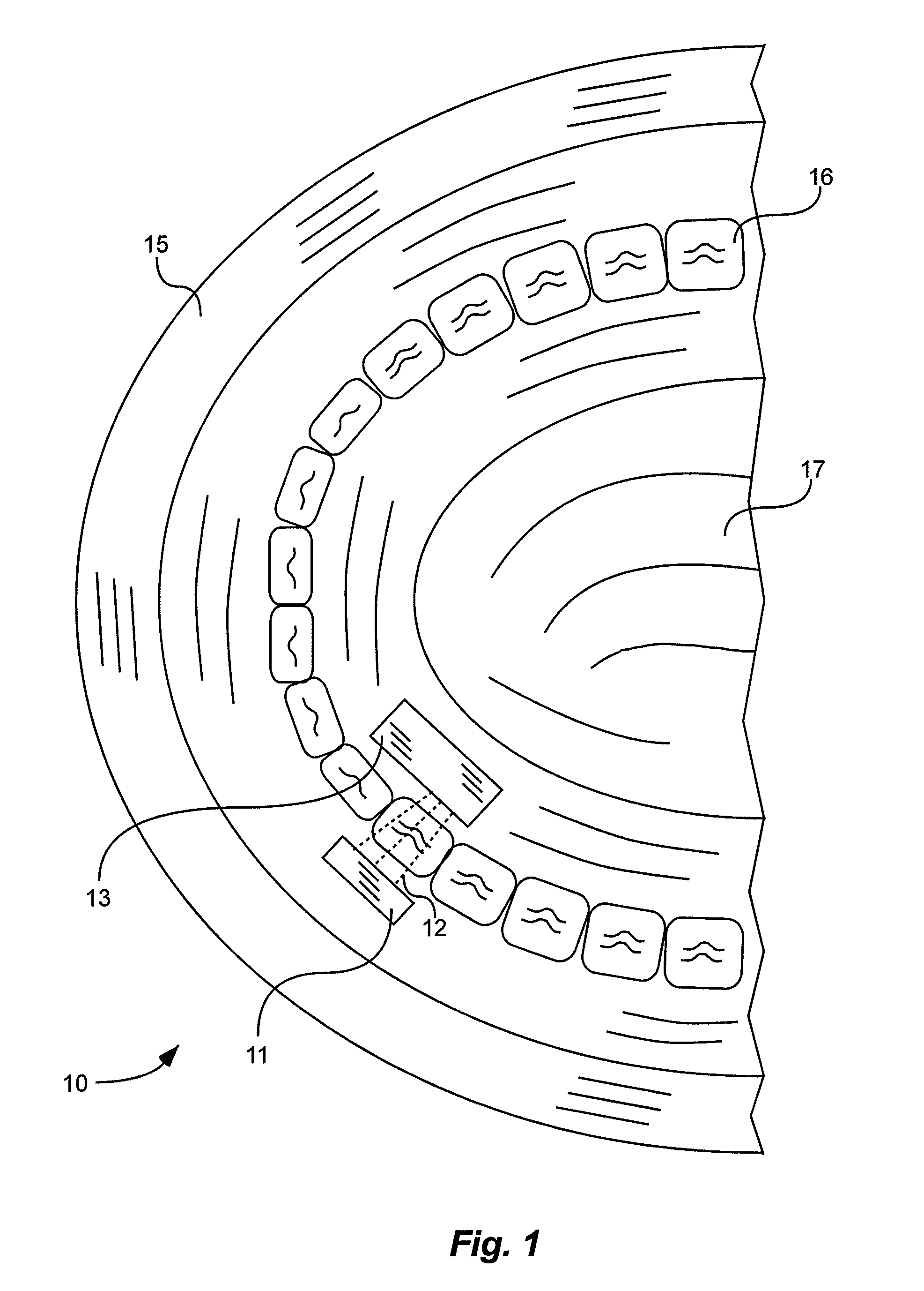
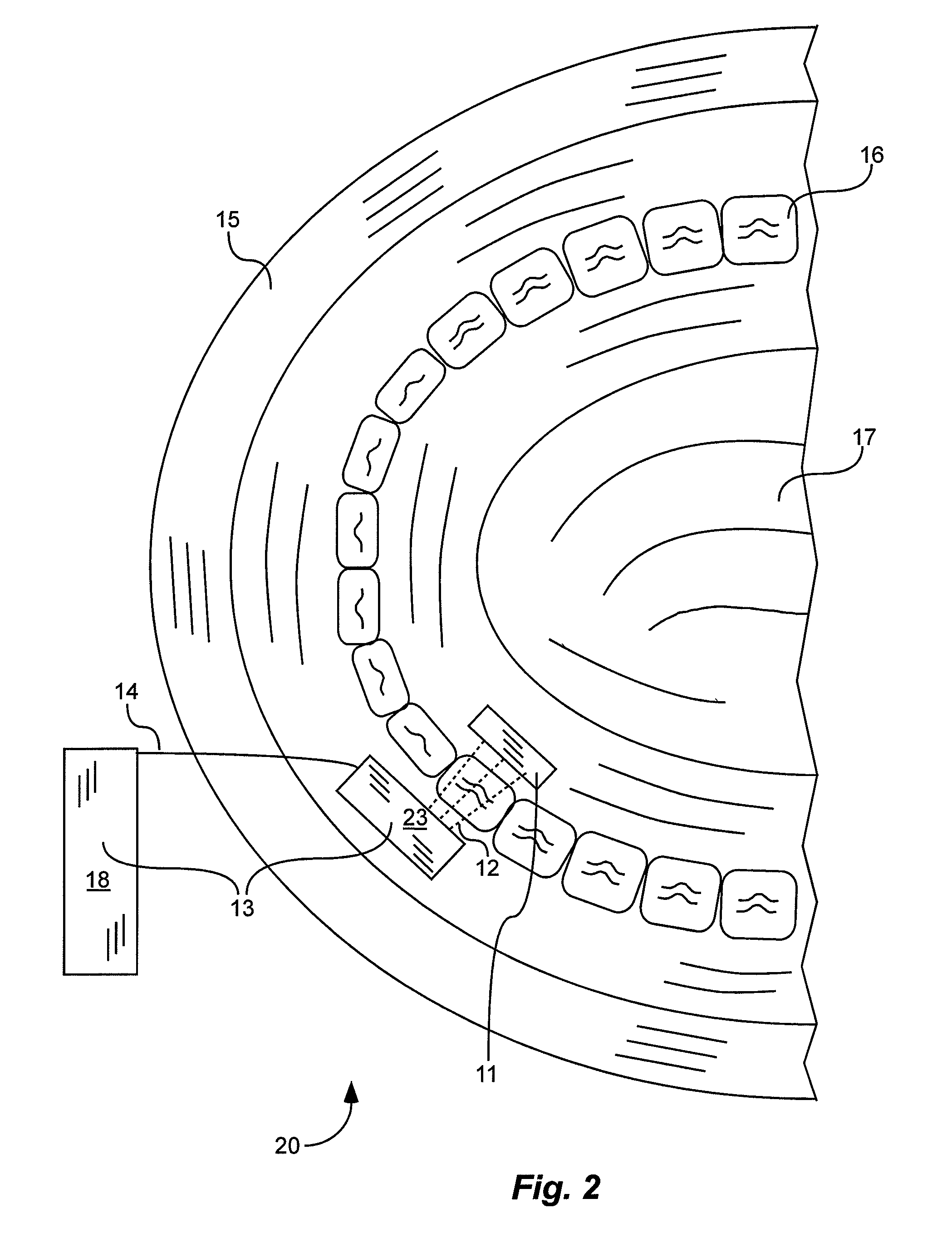
X-ray tube and receiver inside mouth

a receiver and x-ray tube technology, applied in the field of dental x-rays, can solve problems such as incorrect images, and achieve the effect of reducing patient exposure to radiation

Active Publication Date: 2015-11-03
MOXTEK INC
View PDF318 Cites 0 Cited by
  • Summary
  • Abstract
  • Description
  • Claims
  • Application Information

AI Technical Summary

Benefits of technology

The invention is a device and method for taking dental x-rays that reduces patient exposure to radiation. The device includes an x-ray source and an x-ray receiver, with a bite holder creating a gap between them to hold the x-ray source on one side of a tooth and the x-ray receiver on the other. The method involves placing the x-ray source and the receiver on either side of the tooth and emitting the x-rays from the source through the tooth and onto the receiver. The technical effect is a safer and more efficient way to take dental x-rays.

Problems solved by technology

The cheek or lip may also block the medical professional's view, resulting in images taken at incorrect locations.
Increased x-ray flux due to the large gap and due to retakes of the image may expose the patient to extra, undesirable radiation, which can cause health problems.

Method used


Image

  • X-ray tube and receiver inside mouth
  • X-ray tube and receiver inside mouth
  • X-ray tube and receiver inside mouth

Examples


Embodiment Construction

[0022]As illustrated in FIGS. 1-5 and 9, x-ray devices 10, 20, 30, 40, 50, and 90 for dental x-rays are shown comprising an x-ray source 13 and an x-ray receiver 11. The source 13 and the receiver 11 can be sized and configured to be disposed at least partially in a patient's mouth. Configured to be disposed in a patient's mouth means that these units 11 and 13 are shaped and made of materials that will fit properly in the patient's mouth, are designed for patient comfort, and will result in optimal safety for the patient.

[0023]As shown on x-ray device 10 of FIG. 1, at least a portion of the source 13 can be disposed between a tongue 17 of a patient and a tooth 16. At least a portion of the receiver 11 can be disposed between a cheek or lip 15 of the patient and the tooth 16.

[0024]As shown on x-ray device 20 of FIG. 2, at least a portion of the receiver 11 can be disposed between a tongue 17 of a patient and a tooth 16. At least a portion of the source 13 can be disposed between a c...


PUM


Abstract

A method and a device for low x-ray radiation dosage while taking x-ray images of a patient's teeth is disclosed. The method includes use of an x-ray source and receiver positioned at least partially inside the patient's mouth. The device includes an x-ray source and receiver attached together by a bite holder and configured to both be disposed at least partially inside the patient's mouth across a tooth while taking x-ray images of a patient's tooth.

Description

CLAIM OF PRIORITY[0001]This claims priority to U.S. Provisional Patent Application No. 61 / 814,144, filed on Apr. 19, 2013, which is hereby incorporated herein by reference in its entirety.FIELD OF THE INVENTION[0002]The present application is related generally to dental x-rays.BACKGROUND[0003]Typical dental x-rays are performed with an x-ray source or an x-ray receiver disposed outside the mouth of a patient, and the other of the x-ray source or x-ray receiver disposed inside the mouth of the patient. The patient's cheek or lip may force a gap between source or receiver and the tooth. Because of this gap, increased x-ray flux may be needed to obtain an image of the tooth. The cheek or lip may also block the medical professional's view, resulting in images taken at incorrect locations. As a result, the x-ray image may need to be retaken. Increased x-ray flux due to the large gap and due to retakes of the image may expose the patient to extra, undesirable radiation, which can cause he...

Claims


Application Information

Patent Timeline
Patent Type & Authority Patents(United States)
IPC IPC(8): A61B6/14A61B6/00
CPCA61B6/145A61B6/4057A61B6/425A61B6/542A61B6/512
Inventor LEE, SAMUEL SOONHOTIRADO, VICTOR ARMANDOCRAWFORD, DAVID S.
Owner MOXTEK INC
Learn More