

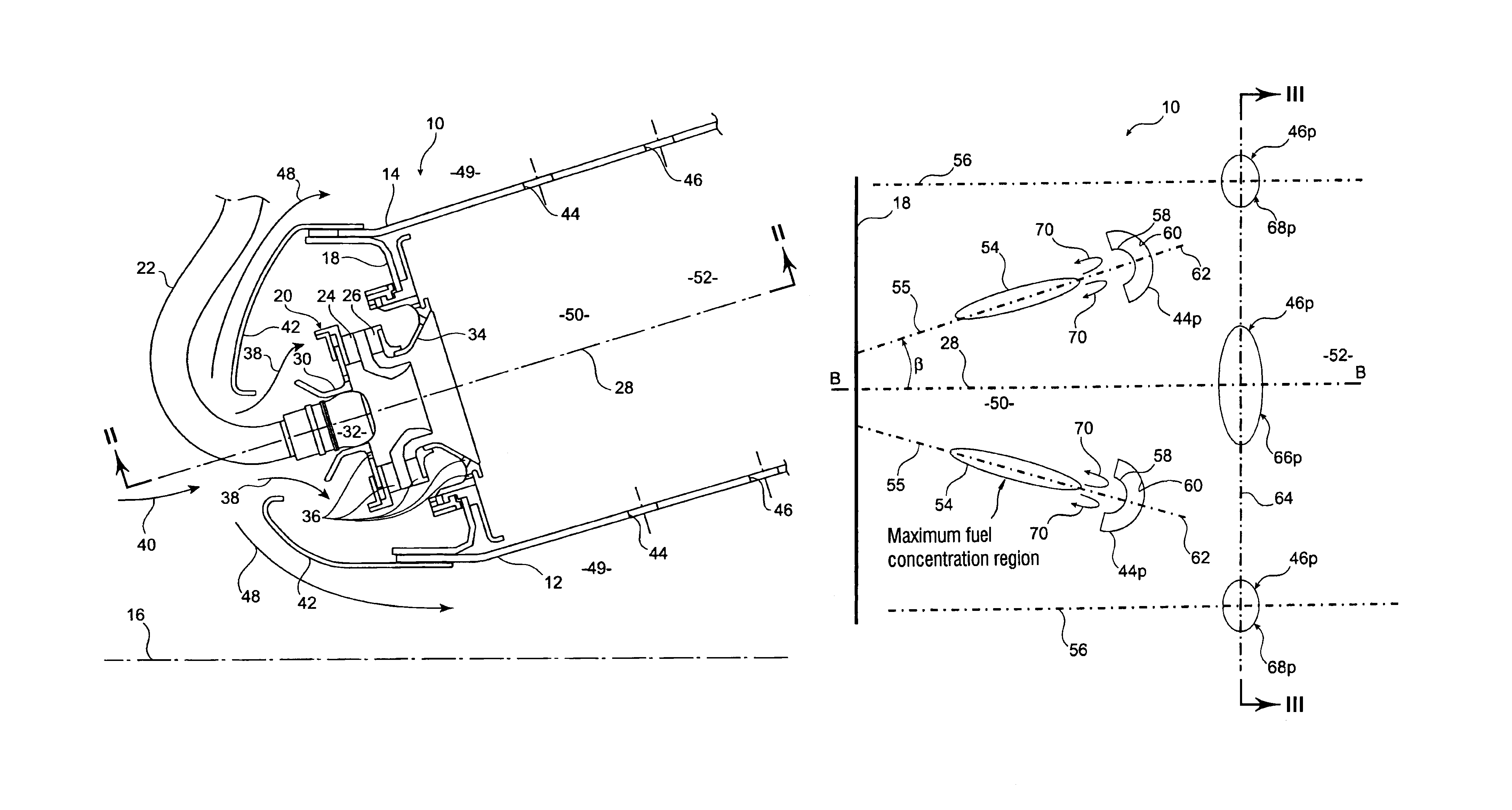
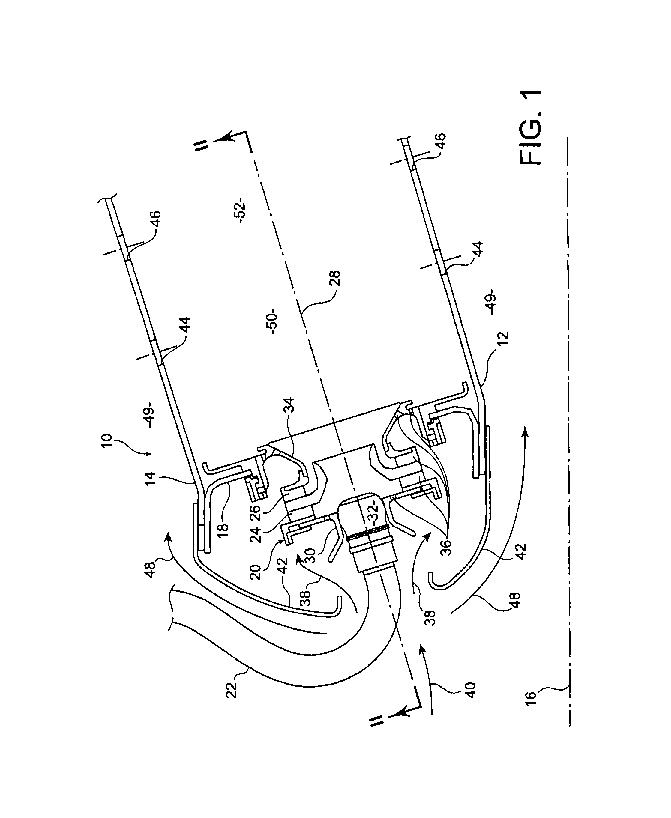
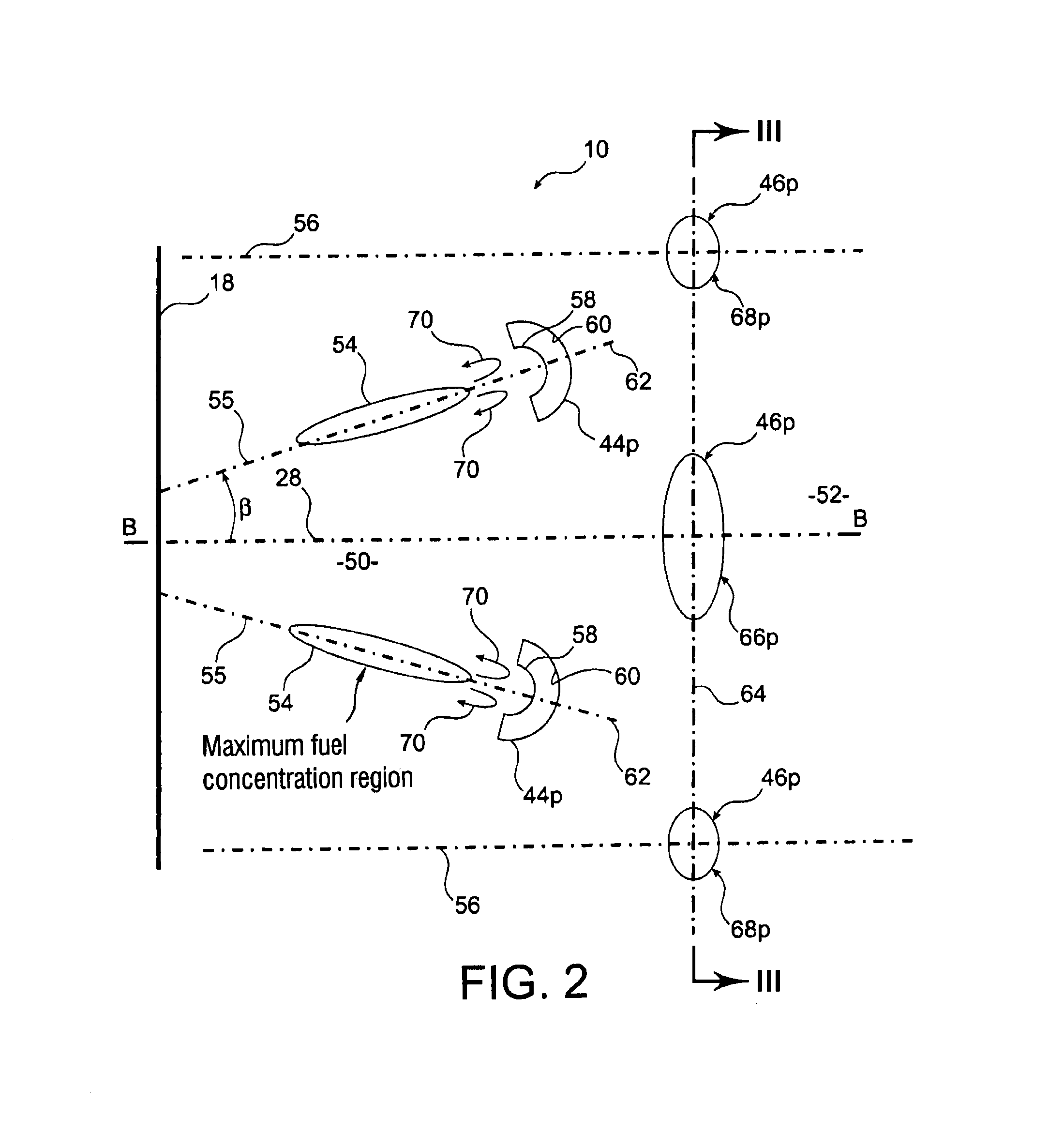
Combustion chamber for a turbomachine including improved air inlets
a combustion chamber and turbomachine technology, which is applied in the direction of machines/engines, efficient propulsion technologies, lighting and heating apparatus, etc., can solve the problems of uniform fuel concentration in the primary zone of the combustion chamber, insufficient temperature profile of the combustion gases being expelled from the combustion chamber,
- Summary
- Abstract
- Description
- Claims
- Application Information
AI Technical Summary
Benefits of technology
Problems solved by technology
Method used
Image

Examples
Embodiment Construction
[0012]One aim of the invention is notably to provide a simple, economic and efficient solution to these problems.
[0013]To this end it proposes a combustion chamber for a turbomachine, including an annular end wall fitted with injection systems regularly distributed around a longitudinal axis of the combustion chamber, each of which has a central fuel emission axis, where the combustion chamber also includes two coaxial annular walls, which are respectively internal and external, connected to one another by the end wall, and including multiple air inlets formed on at least one of these annular walls and opening radially towards the outside relative to the axis of the combustion chamber. According to the invention, the multiple air inlets include inlets of a first type shaped such that the orthogonal projection of each of these inlets in a corresponding projection plane, which passes through the central axis of the injection system closest to the inlet, and which is perpendicular to a...
PUM
 Abstract
Description
Claims
Application Information