

Methods, arrangements and apparatus for utilizing a wavelength-swept laser using angular scanning and dispersion procedures
a wavelength-swept laser and angular scanning technology, applied in the direction of optical radiation measurement, instruments, spectrophotometry/monochromators, etc., can solve the problems of limiting the maximum tuning speed and the sweep frequency previously demonstrated is less than 1 khz limited by finite tuning speeds of filters, so as to facilitate high-speed wavelength-swept light, wide spectral tuning range, and narrow instantaneous line width
- Summary
- Abstract
- Description
- Claims
- Application Information
AI Technical Summary
Benefits of technology
Problems solved by technology
Method used
Image

Examples
Embodiment Construction
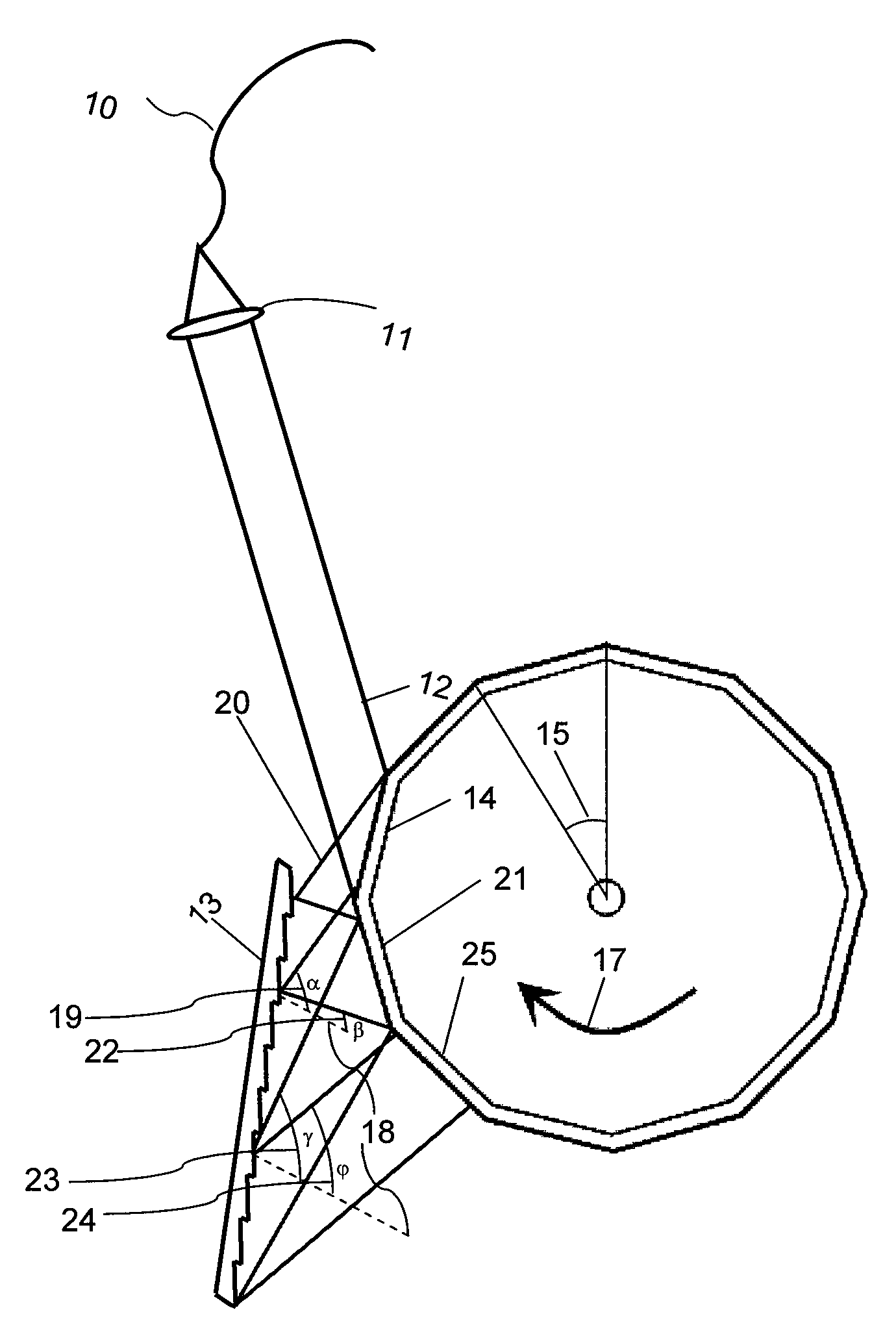
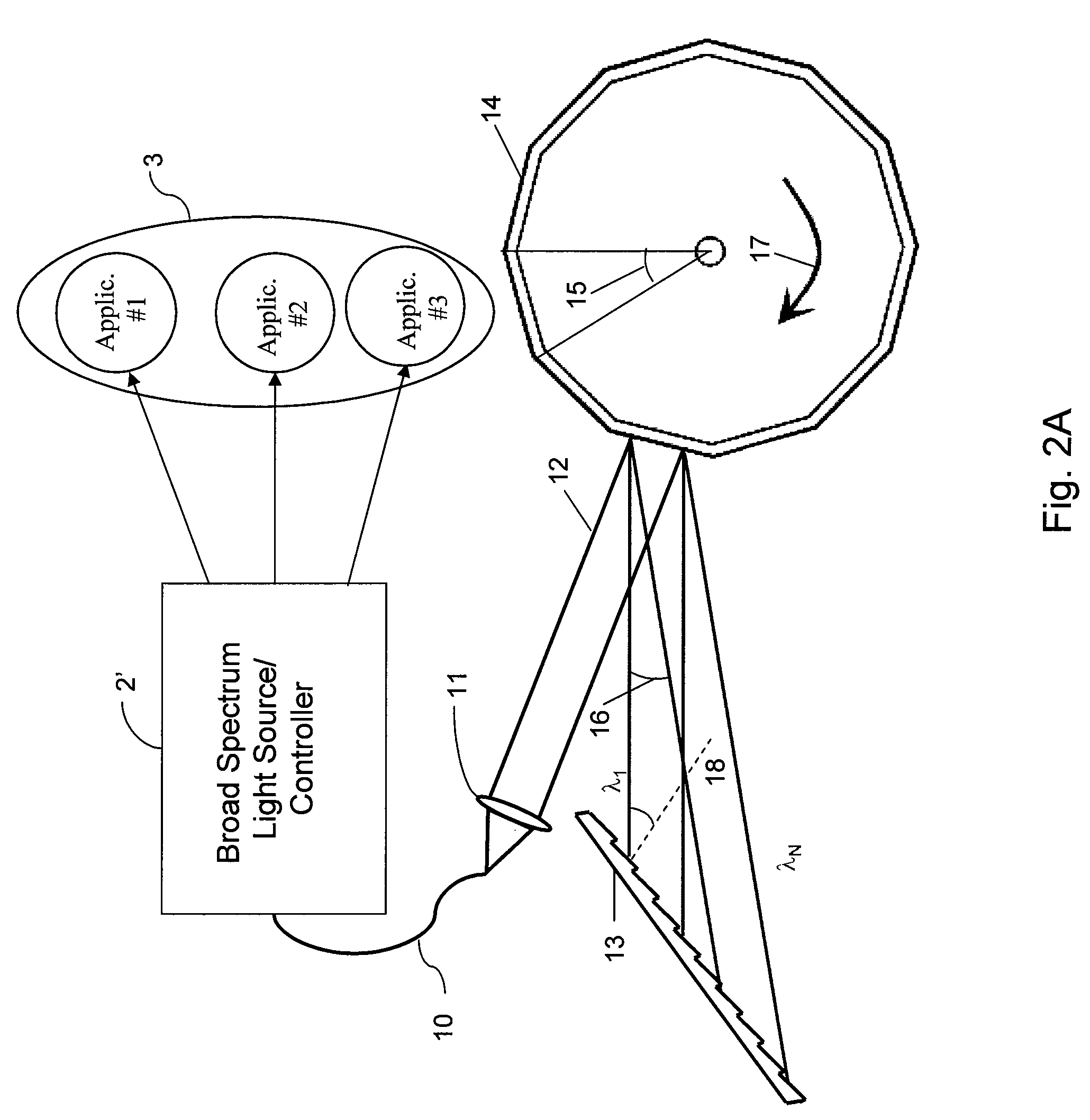
[0007]One of the objectives of the present invention is to overcome certain deficiencies and shortcomings of the prior art arrangements and methods (including those described herein above), and provide exemplary embodiments of arrangements and methods for wavelength tuning and a wavelength-swept laser using exemplary optical wavelength filter systems
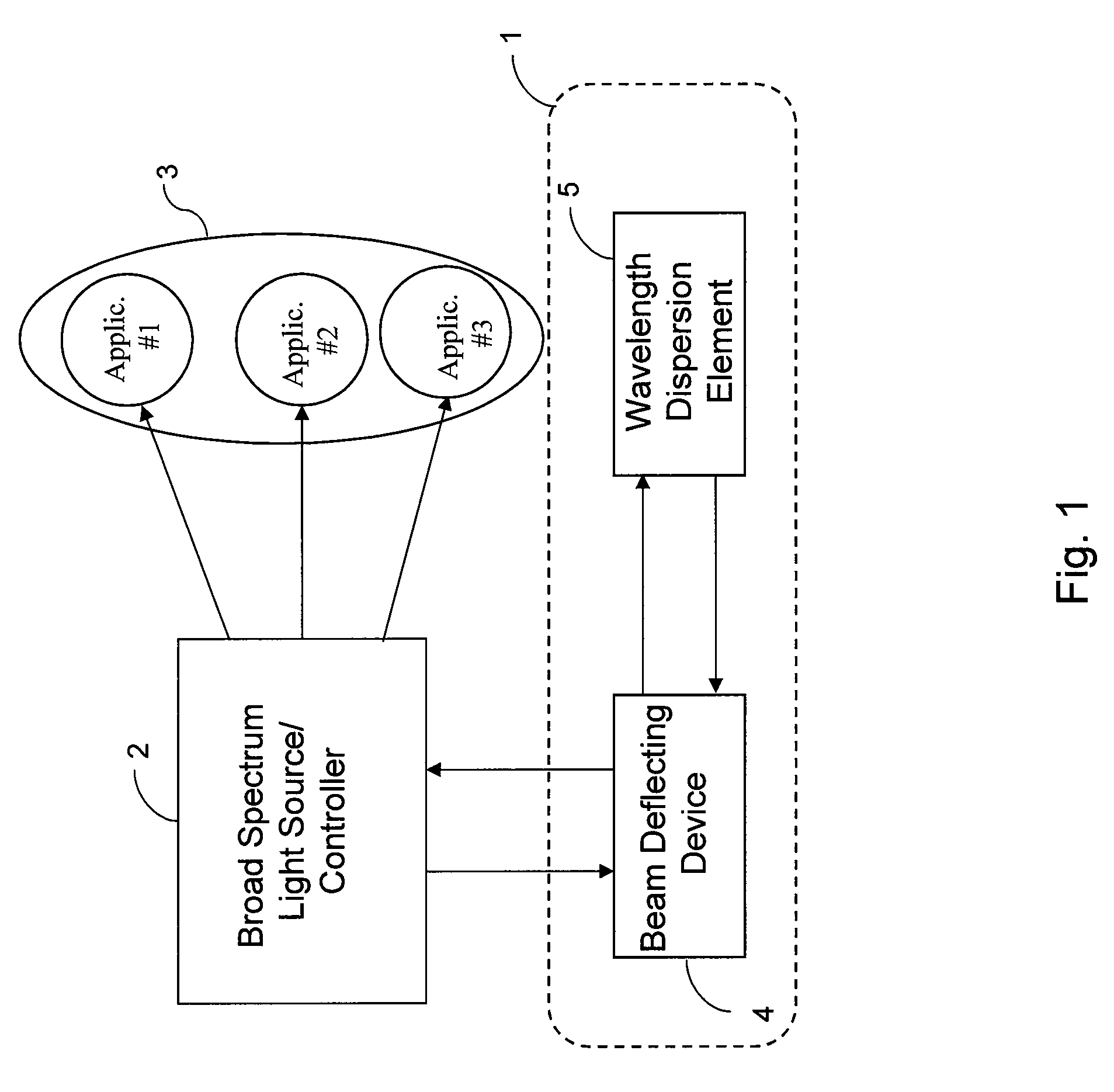
[0008]According to one exemplary embodiment of the present invention, an apparatus and a source arrangement can be provide for light wave filtering which may facilitate high-speed wavelength-swept light with broad spectral tuning range and narrow instantaneous linewidth. In one exemplary embodiment of the present invention, the optical filter can include a diffraction grating (or multiple diffraction gratings or prisms), and an angular scanning element(s) (including, but not limited to, a polygonal mirror, a (multi facets) planar mirror disposed on a rotating shaft, a (multi facets) mirror disposed on a galvonmeter, or an (multi) acousto...
PUM
| Property | Measurement | Unit |
|---|---|---|
| line width | aaaaa | aaaaa |
| sweep frequency | aaaaa | aaaaa |
| width | aaaaa | aaaaa |
Abstract
Description
Claims
Application Information