Sprocket assembly

a technology of brackets and components, applied in the direction of hoisting equipment, belts/chains/gearings, portable lifting, etc., can solve the problems of additional manufacturing costs, and achieve the effect of cost-effective and cost-effectiv

Active Publication Date: 2015-11-10
SRAM
View PDF27 Cites 0 Cited by
  • Summary
  • Abstract
  • Description
  • Claims
  • Application Information

AI Technical Summary

Benefits of technology

[0012]The object is, therefore, for a sprocket assembly that is produced by means of manufacturing methods involving machining, to provide a cost-effective possibility for the provision of a rotationally secure connection between the attachment screw and the sprocket cluster. This object is achieved by dividing the sprocket cluster into at least two components, particularly a separate ring element in addition to the already-existing sprocket cluster. These two components are coupled together in a rotationally fixed manner by means of rotary coupling elements, with knurled teeth being embodied on one of the components that do not have to be formed by machining the sprocket cluster, but rather with the aid of cost-effective methods such as a stamping process.

Problems solved by technology

The production of the above-mentioned knurled feature, which acts as rotary coupling elements, is associated with additional manufacturing costs.

Method used


Image

  • Sprocket assembly
  • Sprocket assembly
  • Sprocket assembly

Examples


Embodiment Construction

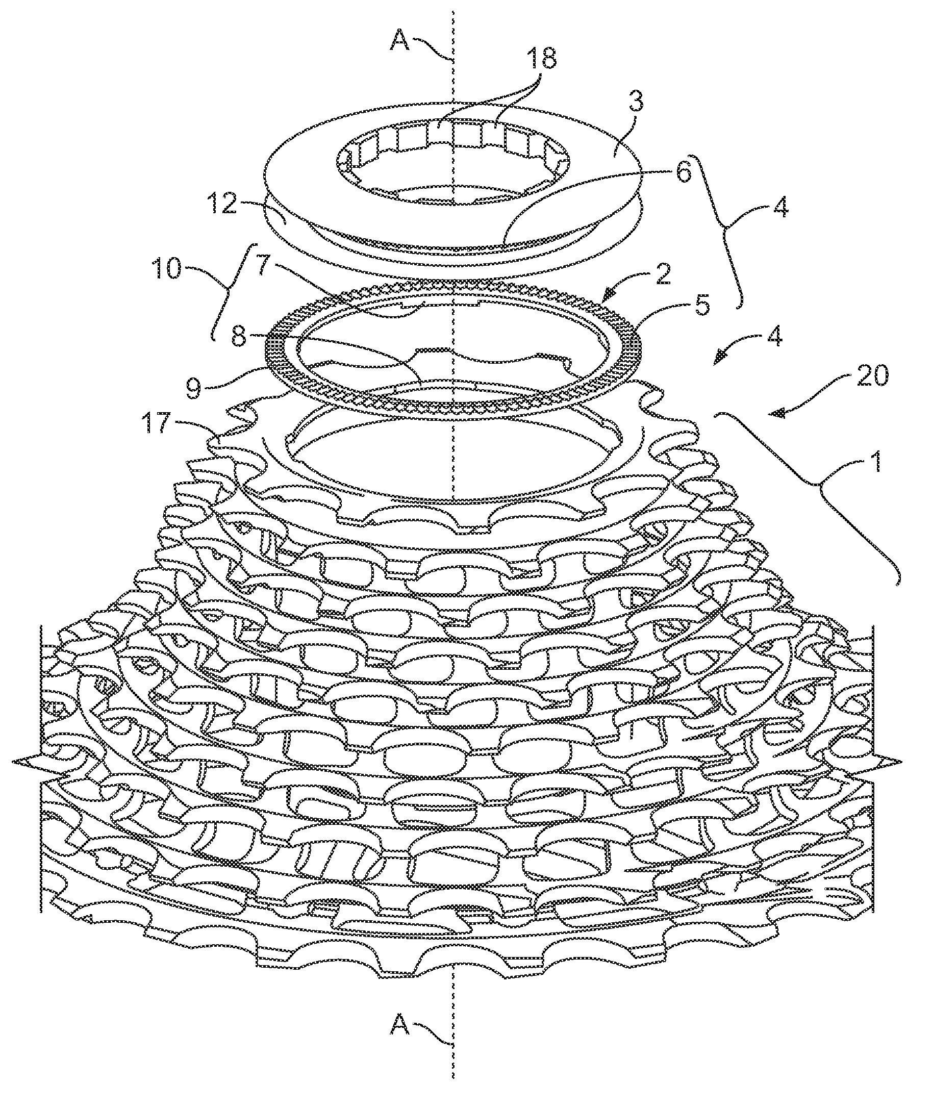
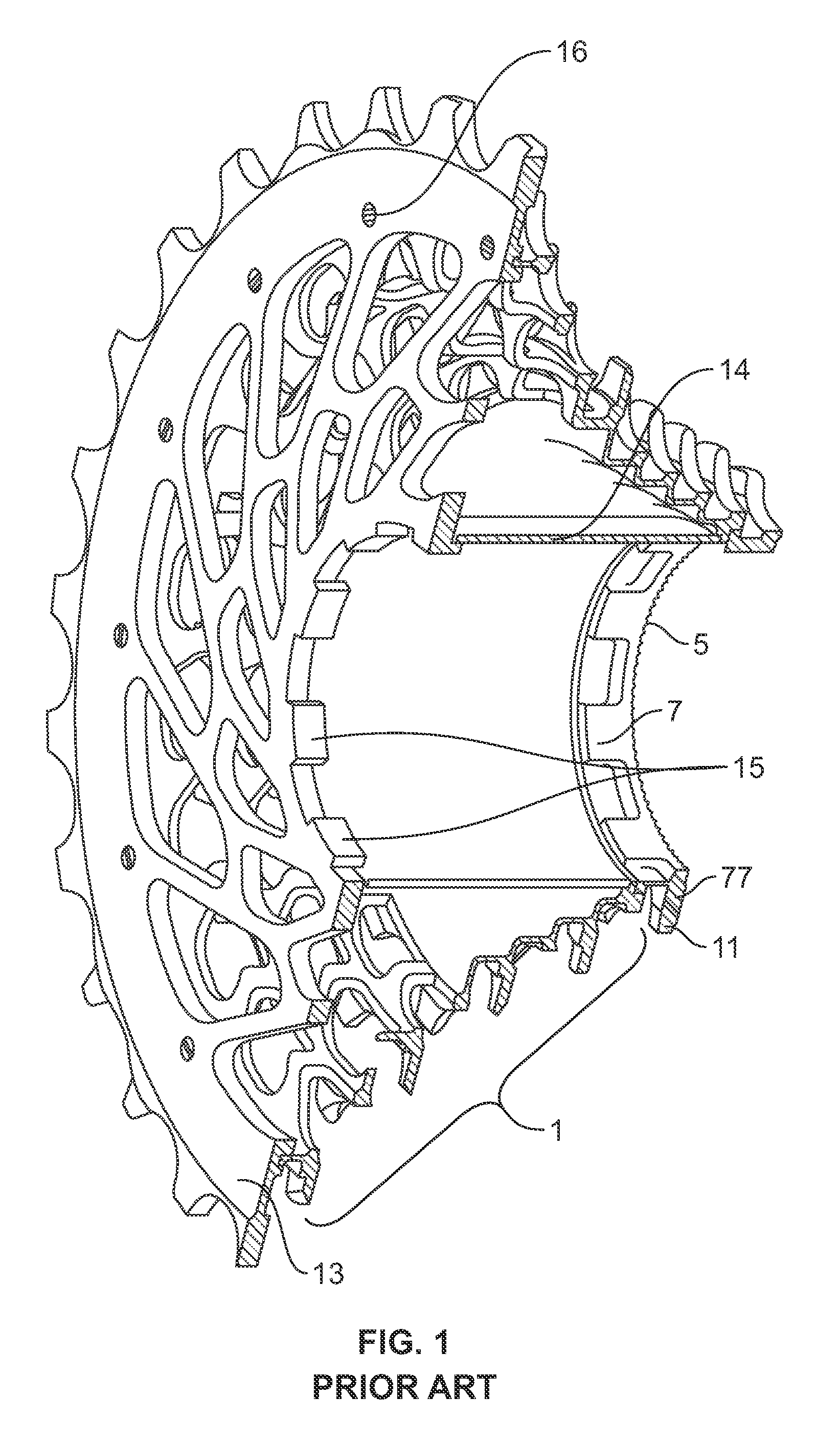
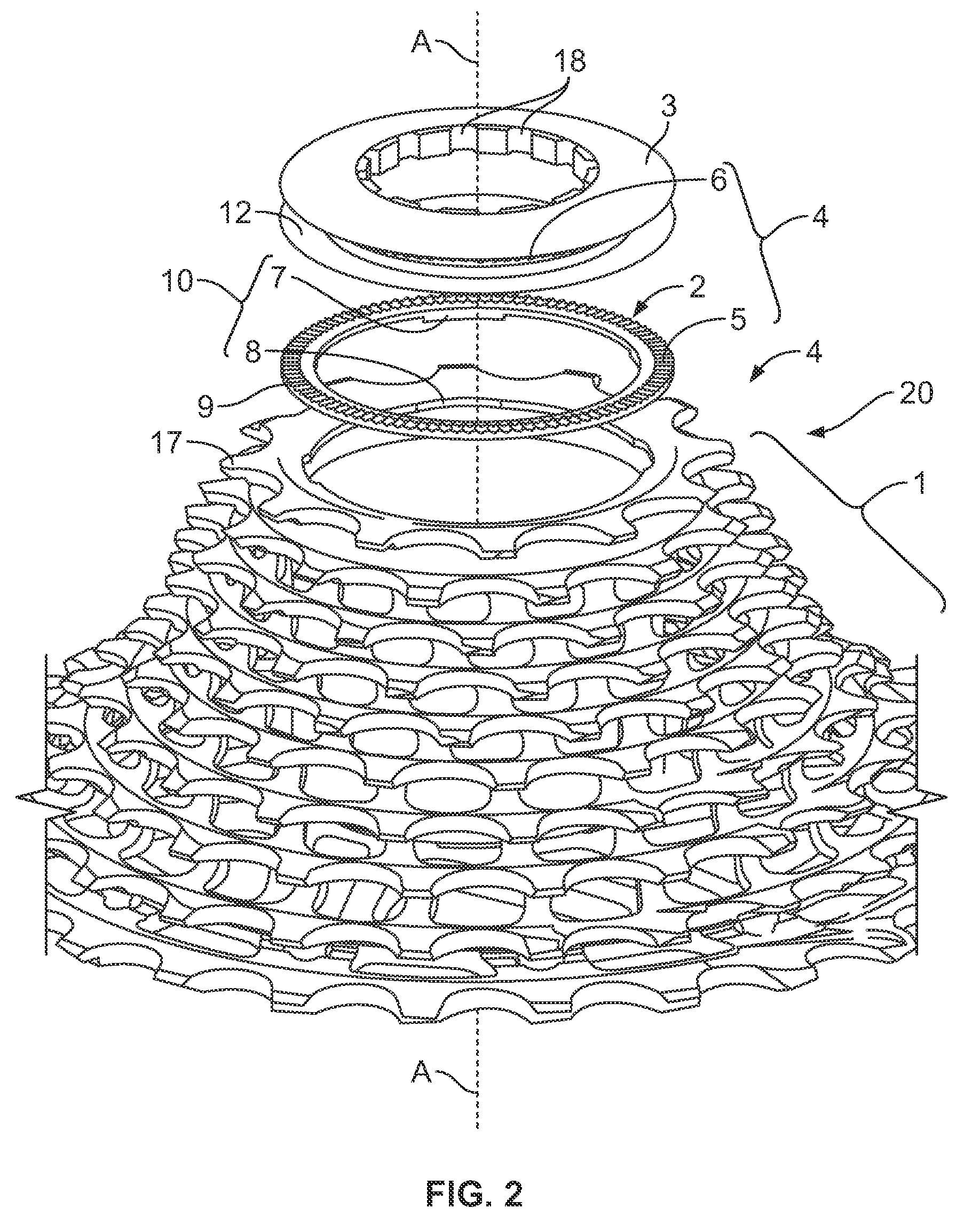
[0021]FIG. 1 shows a prior art one-piece sprocket cluster 1, a cap member 13, a spacer sleeve 14 and a separate smallest sprocket 17, the cluster 1 installable on a driver (not shown) of a bicycle rear wheel hub in a rotatable manner with respect to the hub axle (also not shown). For the purpose of rotary coupling, engaging projections 15 engage on the cap member 13 and first rotation-couplers 7 engage on the smallest sprocket 17 into depressions provided on the driver. Also, for the purpose of rotary coupling, engaging pins 16 engage on the sprocket cluster 1 in corresponding holes on the cap member 13. By means of an attachment screw (not shown), which is arranged in the figure to the right of the smallest sprocket 17, the smallest sprocket, the sprocket cluster 1, the spacer sleeve 14 and the cap member 13 are pre-tensioned against an axial collar of the driver. As this occurs, a stepped support structure of the sprocket cluster 1 is slightly compressed axially until the spacer s...


PUM


Abstract

The invention relates to a sprocket assembly for mounting on a driver of a rear wheel hub of a bicycle. By means of a threaded element, a sprocket cluster and a separately embodied ring element are axially clamped together, and a rotation-coupling device is provided between the sprocket cluster and the ring element. Knurled teeth features on the threaded element and ring element prevent the loosening of the threaded element. Through the separate embodiment of the ring element and sprocket cluster, the respective most suitable manufacturing methods can be used for the two parts and, in the event that the sprocket cluster is manufactured by means of machining methods, the knurled features on the ring element can also be produced in a cost-effective and precise manner through shaping methods.

Description

BACKGROUND OF THE INVENTION[0001]The invention relates to a sprocket assembly for mounting of a driver on a rear wheel hub of a bicycle. The multiple sprocket assembly includes a cluster of sprockets of different sizes for engaging a chain and for transferring a force introduced by the chain to the hub, with the possibility of shifting the chain from one sprocket to another by means of a derailleur.[0002]In some conventional multiple sprocket assemblies, a cassette or multiple sprocket cluster part with a plurality of separate sprockets with different diameters and numbers of chain teeth is arranged on a driver of a hub via a spline-type interface. The teeth of each sprocket engage alternatingly with the chain upon actuation of the derailleur and transfer a torque from the pedaling forces of the rider to the driver via an inner profile that connects the sprockets to the driver splines. Each of these sprockets therefore individually transfers the torque to the driver, as a result of ...

Claims


Application Information

Patent Timeline
Patent Type & Authority Patents(United States)
IPC IPC(8): F16H55/12B62M9/10F16H55/30
CPCB62M9/10F16H55/30
Inventor FLORCZYK, RAYMONDHOLLE, PHILIPP
Owner SRAM
Why Eureka
Try Eureka