Portable containment berm

a containment berm and portability technology, applied in the field of containment berms, can solve the problems of contamination risk, contamination, contamination of surrounding natural resources, human and property hazards, etc., and achieve the effect of reducing damag

Active Publication Date: 2015-11-17
BUCK LARRY RAY +1
View PDF4 Cites 6 Cited by
  • Summary
  • Abstract
  • Description
  • Claims
  • Application Information

AI Technical Summary

Benefits of technology

[0009]Accordingly, there is provided herein, in various embodiments, an easily deployable portable containment berm system that is transportable, may be expeditiously deployed in the field, and provides improved structures for reducing damage that may be caused by vehicles. The present invention seeks to remedy many of the problems found in the prior art discussed above, and other problems not discussed herein.
[0010]In one aspect of the invention, one or more substantially deformable foam support beams are removably attached end-to-end such that the beams form an enclosed perimeter having a shape such as, for example, a square or rectangle. The support beams are preferably constructed of closed-cell foam or other similarly deformable material, allowing the beams to have the rigidity necessary to support the walls of the containment system, but also permitting vehicle wheels to roll over them without causing damage to either the containment system or the vehicle. The foam support beams are wrapped in chemically resistant material such as polyvinyl chloride, which provides protection against damage to the support beams that may be caused by exposure to contaminants.
[0011]In another aspect of the invention, a first protective strip is formed onto the bottom side of the support beams, and extends inwardly towards the center of the perimeter of the containment system. The first protective strip aids in protecting upper layers of the containment system from damage that may be caused by obstructions emanating from the ground or other surface upon which the containment system rests. The first protective strip also helps to protect the containment system from damage that may be caused by vehicle and / or foot traffic. A second protective strip composed of a heavier polyvinyl chloride material may be placed on top of the first protective strip to add further protection from damage to the containment system.
[0013]In an even further aspect of the invention, a first securing material comprising hook and loop fasteners is attached to the underside of the top portion of the side walls, along the outer edge of said side walls. A second securing material comprising hook and loop fasteners formed to mate with the first material comprising hook and loop fasteners, is attached to the top side of the support beams, along an outer edge thereof. Through the use of the aforementioned hook and loop fasteners, the containment basin may be removably secured to the support beams, allowing the containment system to be easily assembled and disassembled in the field.

Problems solved by technology

For example, such inadvertent discharges of contaminants are known to occur in connection with both onshore and offshore oil and gas exploration and extraction operations, which involve the use of numerous chemicals, and produce other by-products that may present a contamination risk if not properly contained.
If left uncontained, such contaminants may be hazardous to surrounding natural resources, humans and property.
One drawback of such known containment systems is that in many instances, they take an inordinate amount of time in which to construct and / or assemble, and deploy in the field.
Another drawback of many containment systems known in the art is that they are not optimally configured for interaction with vehicles.
More specifically, many containment systems are easily damaged by motor vehicles when such vehicles enter and exit the perimeter of said berms, primarily as a result of the vehicle's tires damaging the structure of the berm or tearing the fabric with which the berm is constructed.
An even further drawback of many known containment systems is that they are not easily transportable.

Method used


Image

  • Portable containment berm
  • Portable containment berm
  • Portable containment berm

Examples


Embodiment Construction

Of The Drawings

[0025]Several embodiments of Applicant's invention will now be described with reference to the drawings. In most cases, the items being discussed below correlate to a figure and one or more reference numerals appearing on the attached drawings.

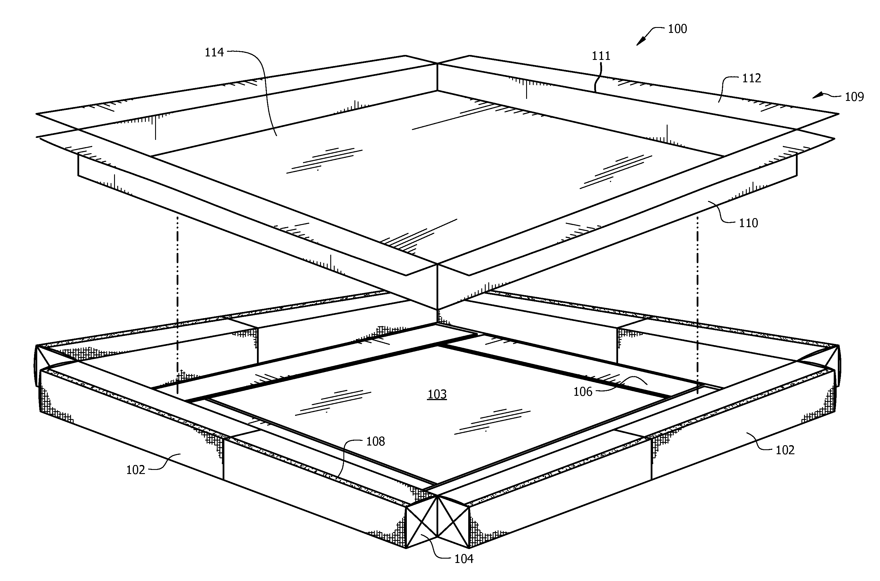
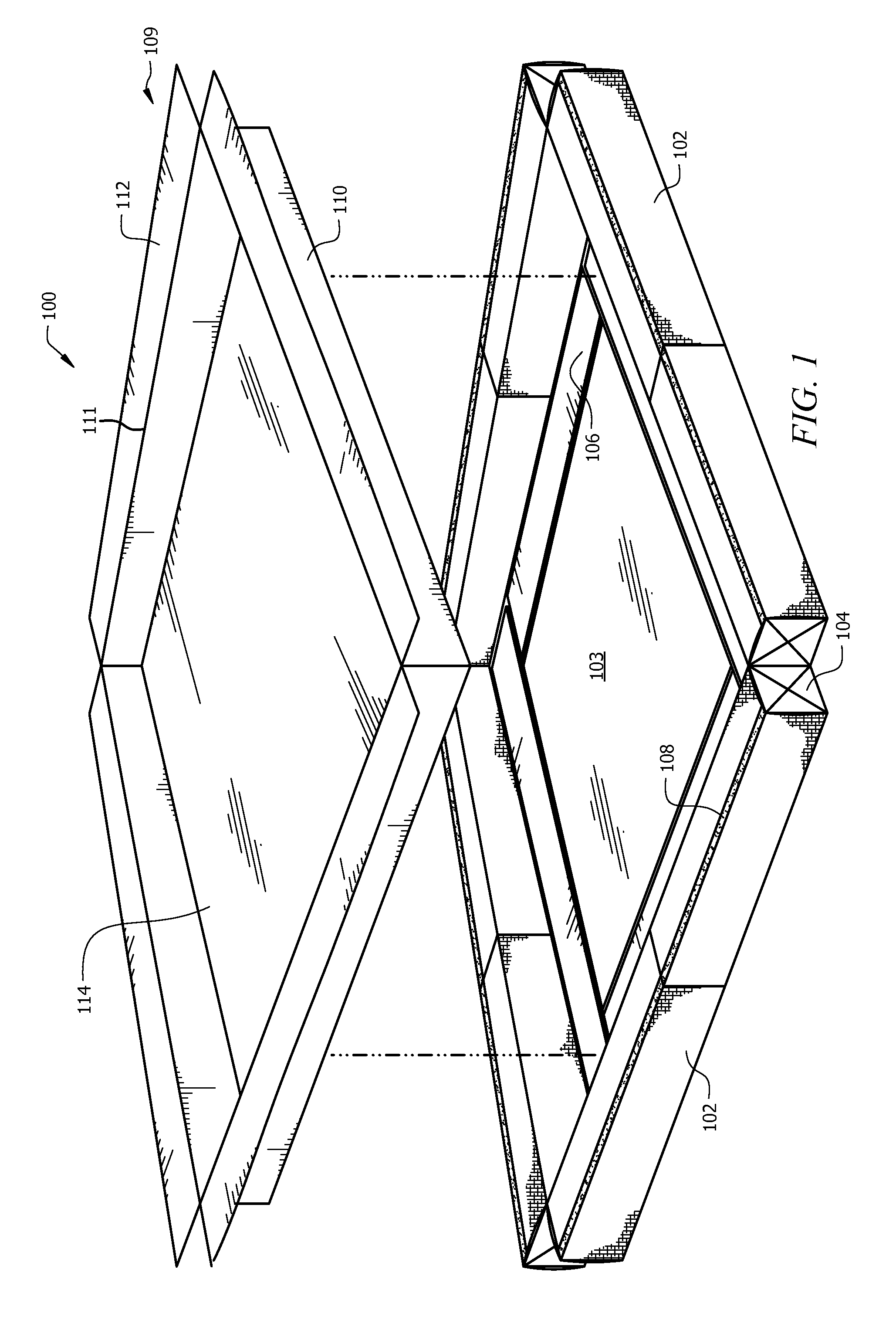
[0026]Referring to FIG. 1, an exploded view of an embodiment of the containment system, showing how the containment basin nests within the perimeter formed by the support beams is depicted therein. The containment system (100) comprises multiple layers of structures configured to prevent the discharge of contaminants and / or to prevent the containment system itself from being damaged. An outer perimeter of the containment system is formed by one or more substantially deformable support beams (102). The support beams (102) are preferably constructed at least partially of closed-cell foam, providing a semi-rigid structure to support the containment system. While closed-cell foam is the material used to construct the support beams o...


PUM


Abstract

An easily assembled and transportable containment system. One or more deformable foam support beams are placed end-to-end to form a containment perimeter. A first protective strip is formed on the underside of at least a portion of the length of each support beam, said protective strips extending inwardly towards the center of the containment system and providing added protection from damage that may be caused due to foot or vehicle traffic. A second protective strip rests on top of the first protective strip and adds even additional protection against damage. A containment basin comprising a floor surrounded by side walls serves to contain discharged chemicals and other potential contaminants until such time as clean-up operations may be completed. The containment basin is removably secured to the support beams via hook and loop fasteners attached to the top sides of the support beams and the top portions of the side walls.

Description

BACKGROUND OF THE INVENTION[0001]1. Technical Field of the Invention[0002]The present invention relates generally to containment devices and in particular, to containment berms that are easily deployable for use in containing spills of potential hazardous waste materials or other contaminants into the ground or other undesirable locations.[0003]2. Description of the Related Art[0004]Numerous industries are involved in conducting operations in which the inadvertent discharge (spill) of hazardous materials and other contaminants (hereinafter collectively, “contaminants”) occurs from time to time. For example, such inadvertent discharges of contaminants are known to occur in connection with both onshore and offshore oil and gas exploration and extraction operations, which involve the use of numerous chemicals, and produce other by-products that may present a contamination risk if not properly contained. The source of such discharges of contaminants that occur during oil and gas operati...

Claims


Application Information

Patent Timeline
Patent Type & Authority Patents(United States)
IPC IPC(8): B65D90/24B65D90/12
CPCB65D90/24B65D90/12
Inventor BUCK, LARRY RAYGAUNTT, EARL G.
Owner BUCK LARRY RAY
Why Eureka
Try Eureka